
The Metallurgical Reality of Soldering Metal Together
Soldering metal together is fundamentally misunderstood by hobbyists as a simple gluing process. In reality, it is a complex metallurgical event. Unlike welding, which melts the base metals, soldering relies on capillary action and the formation of an Intermetallic Compound (IMC) layer between the molten filler alloy and the solid base metal. When you are soldering metal together, the objective is to achieve a continuous Cu6Sn5 (copper-tin) IMC layer that is precisely 1 to 3 microns thick. Too thin, and the joint lacks mechanical shear strength; too thick, and the joint becomes brittle and prone to thermal shock fracturing.
To achieve this consistently, professionals do not rely on guesswork. They use a systematic decision framework. This guide breaks down the exact sequence of material and thermal decisions required to produce IPC-compliant joints in 2026, whether you are working on microelectronics or heavy-gauge RF shielding.
Phase 1: Base Metal Solderability Matrix
The first decision node in our framework is identifying the base metal. The solderability of a metal dictates your flux chemistry and thermal profile. According to The Welding Institute (TWI), surface oxides form at vastly different rates depending on the substrate, requiring tailored chemical reduction strategies.
| Base Metal | Solderability Rating | Primary Oxide Challenge | Required Flux Chemistry |
|---|---|---|---|
| Copper (Bare) | Excellent | Cu2O (Copper(I) oxide) | Rosin Mildly Activated (RMA) |
| Brass / Bronze | Good | Zinc Oxide migration | RMA or Water-Soluble (OA) |
| Nickel / Kovar | Fair | NiO (Highly stable) | Activated Rosin (RA) or Acid |
| Stainless Steel | Poor | Chromium Oxide passivation | Zinc Chloride / Hydrochloric Acid |
| Aluminum | Very Poor | Al2O3 (Instant reform) | Ultrasonic agitation + Specialized Fluoride |
Decision Rule: If you are soldering metal together using Stainless Steel or Aluminum, standard electronics rosin flux will fail 100% of the time. You must step outside standard electronics soldering and utilize aggressive inorganic acid fluxes (followed by rigorous neutralization) or ultrasonic soldering irons that mechanically cavitate the oxide layer.
Phase 2: Flux Chemistry Decision Tree
Flux is the chemical engine of your solder joint. Its job is to reduce metal oxides and lower the surface tension of the molten alloy. Selecting the wrong flux leads to non-wetting or catastrophic corrosion down the line.
1. Rosin Mildly Activated (RMA)
The industry standard for general electronics and copper-to-copper connections. Products like Kester 186 or Indium TACFlux 020 contain mild activators (usually organic acids) that become active at 120°C. RMA leaves a benign, non-conductive residue that can often be left on the board.
2. Water-Soluble (Organic Acid - OA)
Required when soldering metal together in high-humidity environments or when dealing with slightly oxidized brass terminals. OA fluxes are highly aggressive and provide excellent wetting. However, the residue is highly corrosive and hygroscopic. It must be cleaned with heated deionized water (minimum 60°C) within 2 hours of soldering.
3. No-Clean (Synthetic Resin)
Designed for high-volume automated manufacturing. The residue is engineered to remain inert and encapsulate any unreacted activators. Do not use no-clean flux for manual heavy-duty wiring, as the low solids content (often under 5%) provides insufficient oxide reduction for thick gauge wires.
Phase 3: Alloy Selection and Thermal Thresholds
Your choice of solder alloy dictates the minimum thermal energy required to form the IMC layer. In 2026, the market is heavily split between legacy leaded alloys and modern lead-free alternatives, with pricing heavily influenced by global tin and silver commodities.
- Sn63Pb37 (Eutectic): Melts at exactly 183°C (361°F). Because it transitions instantly from solid to liquid (no plastic state), it is highly resistant to cold-joint cracking caused by micro-movements during cooling. Cost: ~$35 per 1lb spool. Best for: Hand-soldering, prototyping, and thick-gauge RF connections.
- SAC305 (Sn96.5/Ag3.0/Cu0.5): The modern lead-free standard. Melts between 217°C and 220°C. The silver content increases the tensile strength and thermal fatigue resistance of the joint. Cost: ~$45 to $55 per 1lb spool in early 2026. Best for: Commercial production, high-vibration automotive electronics, and RoHS compliance.
- Sn95Sb5 (Tin-Antimony): Melts at 232°C (450°F). Used specifically for high-temperature operating environments where a standard SAC305 joint might soften. Cost: ~$60 per 1lb spool. Best for: Aerospace and down-hole drilling sensors.
According to the IPC J-STD-001 standard, when transitioning from leaded to lead-free alloys, the thermal profile must be adjusted to account for the higher liquidus temperature and the poorer wetting characteristics inherent to tin-silver-copper alloys.
Phase 4: Heat Delivery and Dwell Time Limits
When soldering metal together, wattage is a misleading metric. What actually matters is thermal recovery rate and tip geometry. A 65W iron with a thin conical tip will fail to transfer heat into a 14 AWG copper wire connected to a large ground plane, resulting in a cold joint.
The Dwell Time Rule
The NASA-STD-8739.3 specification strictly limits soldering iron dwell time. Prolonged heat exposure causes the IMC layer to overgrow. Once the Cu3Sn layer exceeds 3 microns, the joint becomes brittle. Furthermore, excessive heat delaminates PCB pads and degrades wire insulation.
- Target Dwell Time: 1.5 to 3.0 seconds per joint.
- Maximum Allowable: 5.0 seconds. If the solder has not flowed by 5 seconds, remove the iron, let the joint cool, clean the tip, add fresh flux, and re-evaluate your thermal mass strategy.
Tip Selection Framework
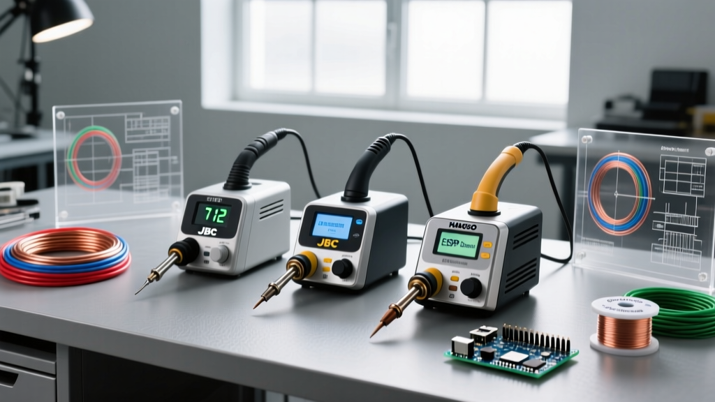
Match the tip's thermal mass to the joint's thermal mass. For heavy ground planes or thick wires, use a bevel or chisel tip (e.g., Hakko T18-D24 or JBC C245-965). The flat surface area maximizes conductive heat transfer, whereas conical tips restrict heat flow to a microscopic point, drastically increasing dwell time and oxidizing the tip rapidly.
Phase 5: Troubleshooting Edge Cases and Failure Modes
Even with the correct framework, edge cases occur. Identifying the visual signature of a failure is critical to correcting the root cause.
Non-Wetting vs. Dewetting
These two failures look similar but have opposite root causes:
- Non-Wetting: The solder balls up and refuses to stick to the base metal, leaving the original metal surface exposed. Root Cause: Heavy oxidation, wrong flux chemistry (e.g., using RMA on stainless steel), or insufficient base metal temperature. The flux failed to reduce the oxides before the solder melted.
- Dewetting: The solder initially coats the metal, but then pulls back into islands, exposing the underlying intermetallic layer. Root Cause: Contamination (silicone, oils, or flux burnout), or the base metal has a metallic plating (like gold or silver) that completely dissolved into the solder bath, leaving a non-solderable underlayer exposed.
Icicle Formation and Bridging
When soldering metal together on tight-pitch terminals, icicles indicate that the solder's surface tension was broken by excessive heat or a lack of flux. To resolve this, lower the iron temperature by 10°C, switch to a smaller chisel tip, and apply a high-quality liquid RMA flux pen to the joint before reflowing.
Summary Checklist for the Workbench
Before applying heat to any project, run through this rapid decision matrix:
- Identify Base Metal: Is it copper, brass, or an exotic alloy? Select flux accordingly.
- Prepare Surface: Mechanically abrade heavy oxidation with fiberglass scratch pens; clean with 99% isopropyl alcohol.
- Select Alloy: Sn63Pb37 for general DIY/RF; SAC305 for RoHS/high-vibration.
- Match Tip Geometry: Use high-surface-area chisel tips for high-thermal-mass joints.
- Enforce Time Limits: Remove the iron within 3 seconds to prevent IMC overgrowth and substrate damage.
By treating the process as a controlled metallurgical reaction rather than a simple adhesive application, you will consistently produce joints that meet rigorous industrial and aerospace reliability standards.