
The Metallurgical Foundation: Choosing Your Alloy
Circuit soldering is not merely about melting metal to join components; it is an exercise in applied thermodynamics and metallurgy. The foundation of any successful solder joint begins with selecting the correct alloy for your specific application, thermal constraints, and compliance requirements. As of 2026, the industry remains split between traditional tin-lead eutectic alloys and modern lead-free alternatives, each demanding distinct thermal profiles.
Alloy Decision Matrix
| Alloy Composition | Melting Point | Wetting & Flow | Best Use Case | 2026 Avg. Cost (per 500g) |
|---|---|---|---|---|
| Sn63/Pb37 (Eutectic) | 183°C (361°F) | Excellent; shiny joints, easy visual inspection | DIY, prototyping, aerospace (exempt), repair | $35 - $45 |
| SAC305 (Sn96.5/Ag3.0/Cu0.5) | 217°C - 220°C | Good; requires higher heat, prone to dull finish | Commercial RoHS-compliant production, SMD | $85 - $110 |
| Sn99.3/Cu0.7 | 227°C (440°F) | Poor; high dross, stiff joints, requires aggressive flux | Budget lead-free through-hole, wave soldering | $40 - $55 |
Expert Insight: For mixed-technology boards (combining SMD and heavy through-hole), Sn63/Pb37 remains the undisputed champion for hobbyists and repair technicians. Its eutectic nature means it transitions directly from solid to liquid without a plastic (semi-solid) phase, drastically reducing the risk of disturbed joints during cooling.
Thermal Mass and Tool Selection Framework
Matching your soldering station to the thermal mass of the circuit board is critical. A common failure mode in circuit soldering is using a low-wattage iron on a board with heavy internal ground planes, resulting in cold joints or prolonged dwell times that delaminate the FR-4 substrate. According to the NASA Electronic Parts and Packaging (NEPP) Program, controlling dwell time and thermal gradients is paramount to preventing pad lifting and micro-cracking in multilayer boards.
2026 Soldering Station Tier List
- Entry-Level / Light SMD (Pinecil V2): Priced around $28, this PD3.1-compatible iron delivers up to 65W. It is exceptional for 0402 to 0805 SMD components and light through-hole work, but struggles with multi-layer ground planes due to its resistive heating element and smaller thermal reservoir.
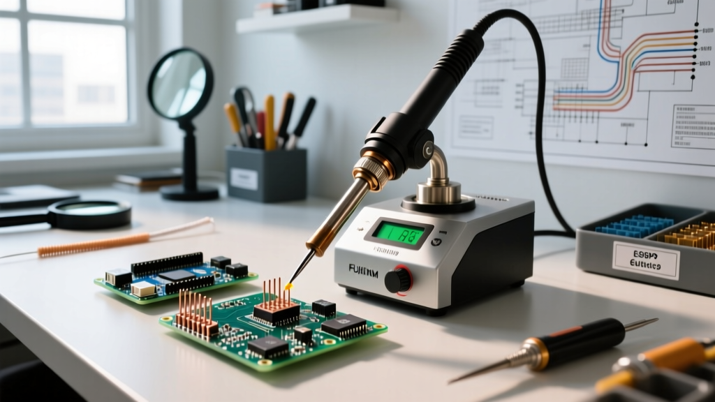
- Mid-Tier Workhorse (Hakko FX-951): At roughly $240, this 75W station uses cartridge-style tips where the heating element is embedded directly in the tip. This provides superior thermal recovery for standard 2-layer PCBs and general DIY circuit soldering.
- Professional / High Thermal Mass (JBC CD-2BE with C245 handles): Retailing near $485 in 2026, JBC's active tip technology delivers 130W directly to the joint. The system detects when the tip touches a component and instantly dumps current to maintain the set temperature, making it the only viable choice for soldering heavy XT90 connectors to 2oz copper planes without preheating.
Flux Chemistry: The Unsung Hero of Wetting
Flux removes oxidation from the copper pads and component leads, allowing the molten solder to form an intermetallic compound (IMC). Choosing the wrong flux chemistry will ruin an otherwise perfect thermal profile.
Flux Selection Guide
- Rosin Mildly Activated (RMA): The standard for general-purpose circuit soldering. Kester 186 liquid flux or standard rosin-core wire provides excellent wetting. It leaves a sticky residue that must be cleaned with 99% isopropyl alcohol (IPA) to prevent long-term dendritic growth in humid environments.
- No-Clean (NC): Designed for modern automated assembly. Amtech NC-559-V2-TF is a tacky no-clean flux widely used for BGA reballing and SMD rework. The residue is non-conductive and non-corrosive, though it can interfere with high-impedance analog circuits or conformal coating adhesion if not cleaned.
- Water-Soluble (Organic Acid - OA): Highly aggressive. Used in industrial environments where boards are washed in specialized aqueous cleaning systems. Never use OA flux for DIY circuit repair, as residual acids will rapidly corrode fine-pitch SMD leads if not perfectly cleaned.
Application-Specific Decision Trees
To streamline your workflow, apply this decision framework based on the component and board topology you are addressing.
Scenario A: Soldering 0402 SMD Passives
- Alloy: SAC305 or Sn63/Pb37 paste/wire (0.3mm diameter).
- Tip Geometry: Micro-conical or 1.0mm Hoof tip.
- Technique: Apply a microscopic dot of Amtech NC-559 tack flux to one pad. Tin the pad. Use fine tweezers to place the component, heating the tinned pad for exactly 1.5 seconds to secure it. Solder the second pad using 0.3mm wire.
Scenario B: High-Current Connectors on Ground Planes
- Alloy: Sn63/Pb37 (1.0mm - 1.5mm diameter) for maximum thermal conductivity and joint strength.
- Tip Geometry: Large Chisel or Bevel (Hoof) tip (e.g., Hakko T12-D24 or JBC C245-1125). Never use conical tips for heavy joints; they lack the surface area for thermal transfer.
- Technique: Preheat the PCB to 100°C using a bottom-side preheater (like a Quick 853A) to reduce the thermal delta. Apply generous RMA flux. Hold the iron at a 45-degree angle to maximize surface contact. Dwell time should not exceed 4 seconds. If the solder isn't flowing, remove heat, add more flux, and try again with a larger tip.
Edge Cases and Failure Mode Analysis
Even with the right tools, circuit soldering presents unique failure modes. Understanding these edge cases is what separates novices from experts. The IPC-A-610 Standard provides the definitive visual criteria for acceptable solder joints, but recognizing the root cause requires deeper analysis.
Troubleshooting Matrix
| Failure Mode | Visual Symptom | Root Cause | Corrective Action |
|---|---|---|---|
| Tombstoning | SMD component stands vertically on one end. | Uneven pad heating; one pad reaches reflow temperature before the other, and surface tension pulls the component upright. | Ensure both pads are heated simultaneously. Use a wider chisel tip or adjust hot air nozzle angle to distribute heat evenly. |
| Cold Joint | Dull, grainy, or lumpy solder appearance; poor mechanical adhesion. | Insufficient heat transfer; flux burned off before solder wetted; movement during the plastic phase. | Reflow with fresh RMA flux. Increase iron temperature by 15°C or switch to a tip with higher thermal mass. |
| Pad Delamination | Copper pad lifts off the fiberglass substrate, sometimes taking the trace with it. | Dwell time exceeded 4-5 seconds; iron temperature set too high (>380°C), exceeding the FR-4 glass transition temperature (Tg). | Use a board preheater to lower the required iron temperature. Never scrape the iron tip against the pad to 'force' heat transfer. |
Final Thoughts on Process Control
Successful circuit soldering relies on a repeatable, controlled process rather than brute-force heating. By systematically evaluating your alloy requirements, matching your tool's thermal recovery to the board's copper weight, and respecting flux chemistry, you eliminate the vast majority of soldering defects. Always prioritize intermetallic compound formation through proper wetting over simply melting solder into a gap. For further reading on advanced reliability standards, consult the latest revisions of the Hakko Technical Guides and IPC workmanship manuals to ensure your builds meet professional-grade reliability metrics.