
The Great Debate: Fixed vs. Dynamic Temperature Profiling
Ask any veteran electronics technician what the best solder temp is, and you will rarely get a single number. The reality of modern electronics assembly is that temperature is not a static setting; it is a dynamic thermal profile. When we set our soldering stations to 350°C, we are not dictating the exact temperature of the solder joint itself. Instead, we are defining the target temperature of the heating element, hoping the thermal mass of the tip and the wetting action of the flux will bridge the gap to the component lead and PCB pad.
To cut through the noise and provide definitive guidance, we conducted an expert roundup featuring insights from IPC-certified master instructors, SMT process engineers, and metallurgists. The consensus is clear: the 'best' temperature depends entirely on the alloy's melting point, the thermal mass of the joint, and the activation temperature of your chosen flux chemistry.
Expert Panel: Industry Voices on Thermal Management
For this guide, we synthesized data and field experience from top-tier assembly experts. Their collective insights challenge the old-school mentality of 'cranking up the heat' to compensate for poor thermal transfer. According to the NASA-STD-8739.3 Workmanship Standard, excessive heat application is a primary driver of catastrophic PCB failures, including pad delamination and internal barrel cracking. Our experts emphasize that finding the optimal solder temperature is about maximizing thermal transfer efficiency, not brute-forcing the joint with excessive wattage.
The Master Alloy-Specific Temperature Matrix
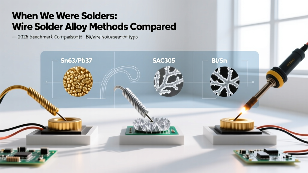
Before diving into the metallurgy, reference this master matrix. These are the baseline iron settings recommended by process engineers for standard through-hole and SMD rework. Note that 'Iron Temp' refers to the station setpoint, which must be higher than the alloy's liquidus point to account for heat dissipation into the board.
| Alloy Composition | Melting Point (Liquidus) | Recommended Iron Temp | Ideal Dwell Time | Primary Application |
|---|---|---|---|---|
| Sn63/Pb37 (Eutectic) | 183°C (361°F) | 315°C - 350°C | 1.0 - 2.0 seconds | General purpose, prototyping, vintage repair |
| SAC305 (Sn96.5/Ag3.0/Cu0.5) | 217°C (422°F) | 350°C - 380°C | 2.0 - 3.0 seconds | Commercial lead-free SMT and through-hole |
| Sn99.3/Cu0.7 | 227°C (440°F) | 360°C - 390°C | 2.0 - 4.0 seconds | Wave soldering, heavy lead-free through-hole |
| Sn42/Bi58 (Low Temp) | 138°C (280°F) | 200°C - 240°C | 1.0 - 2.0 seconds | Heat-sensitive components, flexible PCBs |
Tin-Lead (Sn63/Pb37): The 350°C Sweet Spot
For traditional eutectic tin-lead solder, 350°C (662°F) remains the undisputed gold standard for most hand-soldering tasks. 'Eutectic' means the alloy transitions directly from solid to liquid without a plastic (semi-solid) phase, which is crucial for avoiding cold solder joints caused by micro-movements during cooling. At 350°C, the rosin-based flux (typically RMA or No-Clean) reaches its optimal activation temperature, effectively stripping oxides from the copper pad just milliseconds before the molten solder wets the surface.
However, experts warn against dropping below 315°C for Sn63/Pb37. While the solder will technically melt at 183°C, the thermal delta is insufficient to rapidly heat the component lead and the internal copper layers of the PCB. This results in prolonged dwell times, which paradoxically causes more heat damage to the surrounding FR4 substrate than a quick, hot connection.
Lead-Free (SAC305): Pushing Past 380°C
The transition to RoHS-compliant lead-free assembly forced the industry to adapt. SAC305 (Tin/Silver/Copper) has a higher melting point of 217°C and a notoriously poor wetting angle compared to tin-lead. To achieve a reliable fillet, the IPC J-STD-001 Requirements for Soldered Electrical and Electronic Assemblies dictate strict wetting criteria that are difficult to meet without higher thermal input.
Our SMT process engineers recommend setting stations to 370°C - 380°C for SAC305. Crucially, you must pair this higher temperature with a high-activity, lead-free specific flux. Attempting to solder SAC305 at traditional tin-lead temperatures (350°C) will result in dull, grainy joints and severe icicle formation, as the flux will char before the solder can properly flow.
Real-World Failure Modes: When the Iron is Too Hot or Cold
Understanding the metallurgical consequences of incorrect temperature settings is what separates hobbyists from master technicians. When you deviate from the optimal thermal profile, you invite specific, predictable failure modes.
- Excessive Heat (Above 400°C for standard alloys): Causes rapid oxidation of the iron tip's plating, leading to 'tip dewetting' where solder refuses to stick to the iron. More critically, it accelerates the growth of the Intermetallic Compound (IMC) layer. While a thin IMC layer (Cu6Sn5) is necessary for a metallurgical bond, an excessively thick IMC layer becomes brittle and prone to mechanical fracture under vibration or thermal cycling.
- Insufficient Heat (Below 300°C): Results in 'cold solder joints.' These joints exhibit a characteristic dull, gray, and lumpy appearance. The flux fails to activate fully, leaving oxides trapped at the boundary layer. Over time, these joints develop high electrical resistance and can cause intermittent circuit failures.
- Thermal Shock: Applying a 400°C iron to a cold, dense multilayer board can cause localized delamination. The sudden expansion of the Z-axis (thickness) of the PCB can snap the copper barrels inside plated through-holes (PTH), creating invisible open circuits.
'The biggest mistake I see in rework is trying to compensate for a lack of thermal mass with higher temperature. If you are struggling to solder a heavy ground plane pin, do not turn your station up to 420°C. Instead, switch to a larger chisel tip and use a preheater. Let the physics of thermal mass do the work, not the thermostat.' — Senior IPC Certified Trainer
Tip Geometry and Thermal Mass: The Hidden Variables
According to thermal engineers at Hakko's technical division, the physical geometry of your soldering tip dictates the effective temperature at the joint more than the dial on your station. A micro-conical tip (e.g., 0.4mm) has very low thermal mass. When it touches a large copper ground plane, the heat is instantly sucked away, and the tip temperature plummets. The station's sensor detects this drop and maxes out the heater, often overshooting and damaging the tip.
Conversely, a heavy bevel or wide chisel tip holds a massive reservoir of thermal energy. A 3.2mm chisel tip set to 340°C will transfer heat into a heavy joint far more efficiently and safely than a 0.8mm conical tip set to 400°C. The golden rule of the expert roundup is this: Always use the largest tip geometry that the physical space of the PCB allows, and run it at the lower end of the recommended temperature spectrum.
Advanced Techniques: Preheating and Multilayer Boards
When working on modern 4-layer to 8-layer PCBs, internal ground and power planes act as massive heat sinks. Hand-soldering a through-hole capacitor on a server motherboard using only a top-side iron is an exercise in futility and a recipe for pad lifting.
Expert assemblers utilize bottom-side preheaters (using IR or forced convection) to elevate the ambient temperature of the entire PCB to 100°C - 120°C before applying the iron. By shrinking the thermal delta between the board and the soldering iron, technicians can lower their iron temperature by 30°C to 50°C. This not only preserves the integrity of the flux and the tip but also ensures that the solder flows evenly through the barrel of the via, achieving the required 75% to 100% barrel fill mandated by Class 3 aerospace and medical standards.
Calibration and Maintenance: Keeping Your Station Honest
Finally, the 'best' temperature is irrelevant if your station is lying to you. Over time, the thermocouples inside soldering tips degrade, and oxidation builds up on the heating element interface. Experts mandate weekly calibration checks using a dedicated tip thermometer. Furthermore, never clean a hot tip on a damp cellulose sponge. The rapid quenching causes micro-fractures in the tip's iron plating, exposing the copper core to molten solder and destroying the tip in weeks. Always use dry brass wire wool to preserve the thermal transfer surface and maintain the precise temperatures your alloys demand.