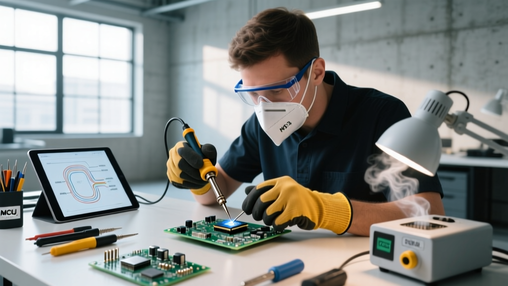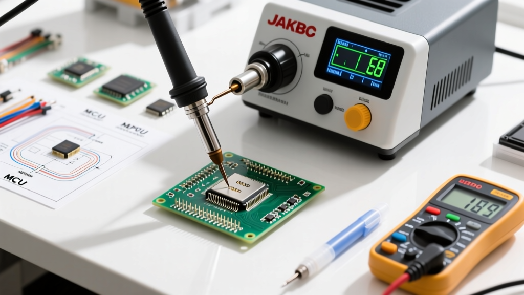

Introduction: The 2026 Landscape of BGA Rework
As of 2026, ball grid array soldering has transitioned from a niche, high-end manufacturing process to a critical skill for advanced repair labs, prototype developers, and serious electronics hobbyists. With the industry pushing toward ultra-fine pitch components (0.25mm and below) and complex heterogeneous 3D packaging, the margin for error has effectively vanished. To bring you the most actionable, up-to-date intelligence, we have synthesized insights from top-tier rework engineers, IPC-certified trainers, and metallurgical experts into this comprehensive roundup.
Whether you are upgrading your lab's rework station or troubleshooting persistent head-in-pillow defects, this guide provides the exact specifications, product models, and thermal profiles you need to succeed.
Expert Consensus: The Core Pillars of BGA Success
We surveyed leading surface-mount technology (SMT) engineers to identify the most common pitfalls in modern BGA rework. The consensus points to three non-negotiable pillars:
'The biggest mistake technicians make in 2026 is ignoring the Moisture Sensitivity Level (MSL) pre-bake. Baking a BGA component at 125°C for 4 to 8 hours before rework isn't optional; it prevents the dreaded popcorn effect caused by trapped moisture expanding during reflow.' — Senior SMT Process Engineer, Tier-1 Aerospace Contractor
'Flux selection dictates your wetting dynamics. Using a generic rosin flux on a 0.3mm pitch BGA guarantees bridging. You need a Type ROL0 no-clean flux with high tack and low residue to hold those micro-spheres perfectly in place.' — Lead Rework Specialist, Microelectronics Repair Lab
Hardware Matrix: Top BGA Rework Stations Compared
Investing in a BGA rework station is a major capital expenditure. Based on current 2026 market pricing and performance metrics, here is how the top three professional systems compare for high-reliability IPC standards compliance.
| Station Model | Approx. Price (2026) | Heating Technology | Temp Accuracy | Best Use Case |
|---|---|---|---|---|
| JBC JTSE Hot Air Station | $4,500 - $5,200 | Convection / Hot Air | ± 2°C | Agile repair labs, mixed-component boards |
| Hakko FR-830 | $6,800 - $7,500 | IR / Hot Air Hybrid | ± 1.5°C | High-volume production, large ground planes |
| Weller IR 3000 | $12,000 - $14,500 | Focused Infrared | ± 1°C | Complex multi-layer server boards, aerospace |
Expert Verdict: For most advanced DIYers and mid-sized repair shops, the JBC JTSE offers the best balance of rapid thermal recovery and cost. However, if you are working on 12-layer server motherboards with massive copper ground planes, the focused IR of the Weller IR 3000 is mandatory to prevent board warpage and delamination.
Consumables Deep Dive: Flux, Paste, and Stencils
Your hardware is only as good as your chemistry. Leading manufacturers like JBC Tools and independent metallurgical labs emphasize that consumable selection must match your specific BGA pitch.
1. Solder Paste Selection
- Type 4 (20-38μm powder): The standard for 0.5mm and 0.4mm pitch BGAs. Use SAC305 (96.5% Sn, 3.0% Ag, 0.5% Cu) for lead-free RoHS compliance.
- Type 5 (10-25μm powder): Mandatory for 0.3mm and 0.25mm ultra-fine pitch. The smaller particle size prevents solder balling and bridging under the component.
- Leaded Alternative: For legacy or specialized aerospace repairs (where lead is permitted), Sn63Pb37 Type 4 paste remains the gold standard due to its lower 183°C melting point and superior wetting.
2. Flux Chemistry
For BGA reballing and placement, tacky flux is superior to liquid flux. Amtech NC-559-V2-TF is widely considered the industry benchmark for 2026. It is a Type ROL0 (Rosin, Low-activity, Zero-halide) no-clean flux that provides exceptional tack to hold 0.2mm solder spheres in place during the pickup process, while leaving a benign, electrically safe residue post-reflow.
3. Stencil Technology
Forget cheap, laser-cut Kapton stencils for reballing. Experts unanimously recommend electropolished stainless steel stencils with a 1:1 aperture ratio. For 0.4mm pitch BGAs, a stencil thickness of 0.12mm (approx. 4.7 mils) yields the optimal solder sphere volume without causing shorts.
The Perfect Thermal Profile: Step-by-Step
A successful BGA reflow relies on a meticulously programmed thermal profile. According to guidelines referenced by NASA's Electronic Parts and Packaging (NEPP) program, controlling the ramp rate is just as critical as the peak temperature. Here is a proven profile for SAC305 lead-free BGA soldering:
- Preheat (Ramp): Ramp from ambient to 150°C at a strict rate of 1.5°C to 2.0°C per second. Why? Faster ramps cause thermal shock, cracking ceramic BGA substrates and micro-vias in the PCB.
- Soak (Dwell): Hold between 150°C and 175°C for 60 to 90 seconds. Why? This allows the flux activators to clean the oxide layers off the BGA pads and ensures the entire board reaches thermal equilibrium, minimizing the delta-T across the component.
- Reflow (Peak): Ramp to a peak temperature of 235°C - 245°C. Time Above Liquidus (TAL - above 217°C for SAC305) must be strictly maintained between 45 and 60 seconds. Why? Insufficient TAL causes cold, grainy joints; excessive TAL dissolves the ENIG gold/nickel barrier layer, leading to brittle intermetallic compounds (IMCs).
- Cooling: Cool down at a maximum rate of 4°C per second. Why? Quenching the board creates micro-cracks in the solder joints due to differing coefficients of thermal expansion (CTE) between the silicon die, substrate, and FR4 PCB.
Common Failure Modes and X-Ray Validation
Visual inspection is useless for BGA soldering; the joints are hidden beneath the component. You must rely on X-ray inspection (AXI) or electrical boundary scan testing. Here are the top three failure modes experts look for:
Head-in-Pillow (HiP) Defect
This occurs when the solder paste on the PCB and the solder sphere on the BGA both melt, but fail to coalesce into a single joint, resting against each other like a head on a pillow. Cause: Usually caused by insufficient flux activity, board warpage during reflow, or oxidation on the BGA spheres. Fix: Switch to a more active flux (e.g., RMA type) or implement a nitrogen-rich reflow atmosphere to prevent oxidation.
Excessive Solder Voiding
Voids are gas pockets trapped inside the solder joint. While some voiding is inevitable, IPC-A-610 standards generally dictate that voiding should not exceed 25% of the total joint area for high-reliability applications. Fix: Use a vacuum rework station or optimize the soak phase of your thermal profile to allow flux volatiles to escape before the solder collapses.
Non-Wet Open (NWO)
The solder sphere melts and wets to the BGA substrate pad, but completely fails to wet the PCB pad. Cause: Contaminated or heavily oxidized PCB pads, often from improper storage or previous rework attempts. Fix: Mechanically clean the PCB pads with a fiberglass scratch pen and apply a fresh coat of highly active tacky flux before rework.
Frequently Asked Questions (FAQ)
Can I use a standard hot air gun for BGA rework?
While technically possible for very large, simple BGAs on single-layer boards, using a standard $50 hot air gun for modern 0.4mm pitch BGAs on multi-layer boards is highly discouraged. Standard hot air lacks the precise thermal profiling, pre-heating capabilities, and optical alignment systems required, leading to a near 100% failure rate on complex boards due to localized overheating and pad lifting.
Is reballing a BGA better than using pre-fluxed replacement spheres?
For automated manufacturing, pre-fluxed spheres are standard. However, for manual rework and repair in 2026, using a stainless steel stencil with high-tack flux (like Amtech NC-559) and loose SAC305 spheres yields superior coplanarity and joint reliability. The stencil ensures every sphere is perfectly aligned before the reflow process even begins.
Do I need an X-ray machine to verify my BGA soldering?
For professional repair and aerospace applications, 2D or 3D X-ray inspection is mandatory to check for HiP defects, bridging, and voiding percentages. For hobbyists without access to a $50,000 X-ray machine, the best alternative is thorough functional testing combined with strict adherence to validated thermal profiles and high-quality tacky flux to minimize hidden defects.