
Decoding the Raspberry Pi4 Pinout: A Hardware Baseline
For hardware engineers, robotics developers, and smart home integrators, the 40-pin GPIO header is the true lifeblood of any single-board computer project. While newer boards have entered the market, the Raspberry Pi4 pinout remains the industry standard reference for HAT (Hardware Attached on Top) compatibility and embedded prototyping. Powered by the Broadcom BCM2711 SoC, the Pi 4 Model B introduced critical shifts in peripheral routing, power delivery, and bus multiplexing compared to its predecessors and even its successor, the Pi 5.
Understanding the physical and electrical realities of this header is not just about memorizing pin numbers; it is about understanding current sourcing limits, alternate function multiplexing (ALT0-ALT5), and logic-level tolerances. In this hardware comparison, we dissect the Pi 4 GPIO architecture against the Pi 3B+ and Pi 5 to help you design robust, failure-resistant circuits.
Generational GPIO Comparison: Pi 3B+ vs Pi 4 vs Pi 5
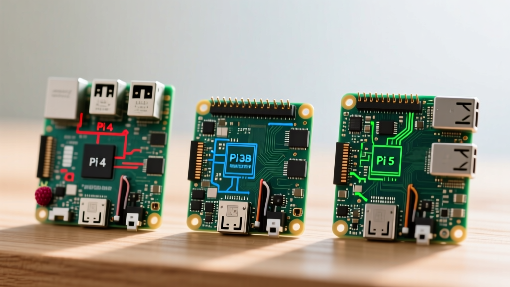
Before wiring up sensors or motor drivers, it is crucial to understand how the Pi 4's hardware interfaces stack up against the older BCM2837B0 (Pi 3B+) and the newer BCM2712 (Pi 5). Below is a technical comparison of the core GPIO capabilities.
| Hardware Feature | Pi 3B+ (BCM2837B0) | Pi 4 Model B (BCM2711) | Pi 5 (BCM2712) |
|---|---|---|---|
| Logic Level | 3.3V (5V Tolerant on I2C) | Strict 3.3V | Strict 3.3V |
| Total 3.3V Rail Current | ~50mA | ~50mA (Dedicated Regulator) | ~50mA (Dedicated) |
| Hardware PWM Channels | 2 (PWM0, PWM1) | 2 (PWM0, PWM1) | 4 (Enhanced Routing) |
| Default I2C Buses | 1 (I2C1) | 1 (I2C1), up to 6 via Mux | 1 (I2C1), up to 6 via Mux |
| SPI Chip Selects (CS) | 2 (Default) | 2 (Default), up to 3 via Mux | 2 (Default), up to 3 via Mux |
| UARTs on Header | 1 (Mini-UART default) | 1 (Mini-UART default) | 1 (UART10 default) |
Power Rail Tolerances and Current Sourcing
A common misconception when exploring the official Raspberry Pi hardware documentation is that the 3.3V pins (Pins 1 and 17) can power external modules like relays or high-draw LED matrices. On the Pi 4, the 3.3V rail is generated by a dedicated switching regulator, but it is strictly capped at approximately 50mA for external GPIO use. Exceeding this limit will trigger brownouts, cause the Pi 4 to randomly reboot, or permanently damage the PMIC (Power Management IC).
The 5V pins (Pins 2 and 4) are directly tied to the USB-C power input. If you are using a high-quality 5V/3A power supply, you can safely draw up to 1.5A from the 5V GPIO pins, provided you account for the Pi 4's own baseline power consumption of roughly 2.5W to 6W under load.
BCM2711 Alternate Functions and Multiplexing Realities
The true hardware advantage of the Raspberry Pi4 pinout lies in the BCM2711's flexible GPIO multiplexing matrix. Unlike simpler microcontrollers where a pin is hardcoded to a specific peripheral, the Pi 4 allows you to reassign almost any GPIO pin to one of six alternate functions (ALT0 through ALT5). According to the BCM2711 Peripherals Datasheet, this unlocks massive potential for sensor fusion and industrial automation.
Unlocking Hidden I2C and SPI Buses
By default, the Pi 4 exposes I2C1 on GPIO 2 (SDA) and GPIO 3 (SCL). However, if you are building a robot with multiple LiDAR sensors, IMUs, and environmental monitors, a single I2C bus will quickly bottleneck due to address collisions and capacitance limits. By editing the config.txt file and applying device tree overlays, the Pi 4 can route I2C3, I2C4, I2C5, and I2C6 to various GPIO pins via the ALT5 function. This allows you to run up to five independent hardware I2C buses simultaneously—a massive upgrade over the Pi 3B+, which struggled with software-based I2C bit-banging.
Hardware PWM Limitations and Audio Routing
When designing motor controllers or LED dimmers, hardware PWM is essential for jitter-free signals. The Pi 4 features two dedicated hardware PWM channels (PWM0 and PWM1). These can be mapped to GPIO 12, 13, 18, and 19. However, hardware engineers must note that GPIO 18 and 19 are also tied to the I2S audio interface (PCM_CLK and PCM_FS). If your project requires high-fidelity DAC audio output alongside precise motor control, you must carefully plan your pin assignments to avoid peripheral conflicts, or rely on software PWM (which introduces CPU-dependent jitter) for the remaining pins.
UART Routing: The Bluetooth and Console Conflict
One of the most notorious hardware quirks of the Pi 4 involves the UART (Universal Asynchronous Receiver-Transmitter) pins. On the Pi 4, the high-performance PL011 UART is hardwired to the onboard Bluetooth module. The UART exposed on the GPIO header (GPIO 14 TXD and GPIO 15 RXD) is the secondary 'mini-UART', which lacks a stable baud rate clock and is prone to data corruption at high speeds.
If your project involves communicating with a GPS module, an Arduino, or a serial console, you must disable the Bluetooth module to route the PL011 UART back to the GPIO header. This is achieved by adding dtoverlay=disable-bt to your /boot/config.txt file and disabling the hciuart systemd service. The newer Pi 5 handles this slightly better with dedicated UART routing, but on the Pi 4, this firmware-level intervention is mandatory for reliable serial hardware communication.
Real-World Failure Modes: Backpowering and Logic Level Clashes
Designing a custom PCB or wiring a breadboard based on the definitive Pi4 pinout guide at Pinout.xyz requires strict adherence to voltage thresholds. The BCM2711 SoC operates at 1.8V internally, with level shifters bringing the GPIO pads to 3.3V. It is not 5V tolerant.
Critical Warning: Connecting 5V logic outputs (such as from an Arduino Uno, standard 5V I2C displays, or unshielded automotive sensors) directly to the Pi 4 GPIO pins will force current through the SoC's internal ESD clamping diodes. While these diodes might survive brief transients, continuous 5V exposure will permanently destroy the GPIO pad and potentially short the entire BCM2711 chip.
To interface 5V hardware with the Pi 4, always use bidirectional logic level shifters, such as those based on the BSS138 MOSFET, or dedicated ICs like the TXB0108.
Another severe failure mode is backpowering. Injecting 5V into Pin 2 or Pin 4 from an external battery pack or motor driver bypasses the Pi 4's USB-C Power Delivery (PD) negotiation circuitry and the onboard polyfuse. If your external 5V source experiences a voltage spike (e.g., reaching 5.5V or higher during inductive load switching), it will backfeed into the USB-C port. This can fry the motherboard of any laptop connected to the Pi 4 via USB for serial debugging. Always use Schottky diodes or ideal diode controllers when merging power sources on the Pi 4's 5V rail.
Summary for Hardware Designers
The Raspberry Pi 4 remains a powerhouse for embedded projects, provided its hardware boundaries are respected. Its 40-pin header offers unparalleled flexibility through BCM2711 multiplexing, but demands rigorous power management and strict 3.3V logic adherence. By understanding the differences in PWM routing, I2C bus expansion, and UART conflicts compared to the Pi 3 and Pi 5, you can engineer resilient, production-ready SBC integrations without falling victim to common silicon-level pitfalls.