
The Hardware Ecosystem: Choosing Your Raspberry Pi and Camera
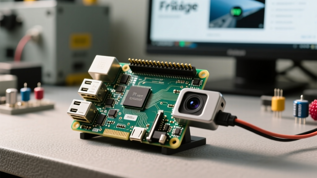
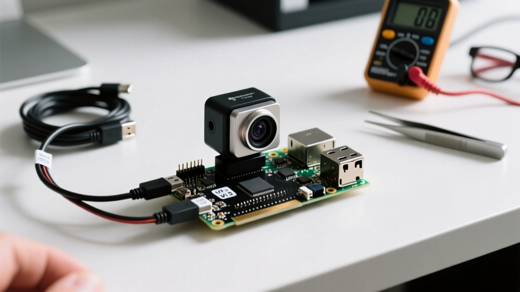
When building a smart home node, a wildlife trap, or a basic computer vision project, pairing a Raspberry Pi and camera module is the most logical starting point. However, the ecosystem has evolved significantly. The days of simply plugging in a V1 camera and running raspistill are over. Today, you must navigate different sensor architectures, physical connector variations between Pi generations, and a completely modernized software stack.
Before touching any ribbon cables, you must select the right optical hardware for your specific use case. The official Raspberry Pi foundation currently supports three primary camera generations, each with distinct advantages and price points.
Official Camera Modules vs. Use Cases
| Module | Sensor | Resolution | Avg. Price | Best For |
|---|---|---|---|---|
| Camera Module V2 | Sony IMX219 | 8 Megapixel | $25 | Basic timelapse, legacy projects, low-budget setups |
| Camera Module 3 | Sony IMX708 | 12 Megapixel | $30 - $50 | Smart home security, HDR imaging, autofocus projects |
| HQ Camera | Sony IMX477 | 12.3 Megapixel | $50 + Lens | Macro photography, telescopes, specialized optics |
For beginners in 2026, the Camera Module 3 is the undisputed sweet spot. It introduces Phase Detection Auto Focus (PDAF) and Hardware HDR, which are managed automatically by the Pi's Image Signal Processor (ISP). If you are attempting to read license plates or monitor a bird feeder, the IMX708 sensor's superior low-light performance justifies the slight premium over the aging V2 module.
Physical Installation: Ribbon Cables and CSI Port Variations
The most common point of failure for beginners is the physical connection between the camera's Flexible Printed Circuit (FPC) ribbon and the Pi's Camera Serial Interface (CSI) port. These are Zero Insertion Force (ZIF) connectors, and they are incredibly fragile.
The Pi 4 vs. Pi 5 Connector Trap
One of the most critical hardware details often missed in older tutorials is the physical difference in CSI ports across board generations. The Raspberry Pi 4 Model B uses a standard 15-pin, 1mm pitch CSI connector. However, the Raspberry Pi 5 utilizes a smaller, denser 15-pin, 0.5mm pitch connector (shared with the Pi Zero series) to accommodate dual CSI/DSI lanes on the board.
- If using a Pi 4: The standard 15-pin ribbon cable included with the V2 and Module 3 cameras will plug in perfectly.
- If using a Pi 5: You must purchase a specific "Pi 5 Camera Cable" (15-pin 0.5mm to 15-pin 1mm) to adapt the standard camera ribbon to the Pi 5's smaller port. Forcing a standard cable into a Pi 5 will destroy the connector.
Proper ZIF Connector Technique
- Gently pry the black plastic locking collar upward using your fingernails or a plastic spudger. Do not use metal screwdrivers; you will snap the collar.
- Slide the ribbon cable into the slot. Orientation is critical: The blue tape (or stiffener) on the ribbon cable must face away from the board's PCB and towards the outer edge of the connector (or upwards, depending on the board layout).
- Press the black collar back down evenly to lock the pins into the cable's contacts.
Software Configuration: The Shift to libcamera
If you are following a tutorial from 2020 that tells you to type raspistill -o image.jpg, close the tab. The legacy camera stack was deprecated and completely removed from Raspberry Pi OS (Bullseye and Bookworm releases). The modern standard is the libcamera Software Stack, an open-source framework that directly interfaces with the Pi's ISP and Linux V4L2 subsystems.
Essential CLI Commands for Testing
Once your hardware is seated and your Pi is booted into Raspberry Pi OS (Desktop or Lite), open your terminal and verify that the OS recognizes the I2C EEPROM on the camera module.
libcamera-hello -t 0
This command initializes the camera and opens a preview window (if running a desktop environment) or streams to the DRM buffer. The -t 0 flag keeps the preview open indefinitely until you press Ctrl+C. If the sensor is detected, you will see terminal output detailing the sensor mode, resolution, and framerate.
To capture a high-resolution still image utilizing the ISP's HDR pipeline:
libcamera-jpeg -o test_shot.jpg --hdr
For recording a 10-second H.264 video clip:
libcamera-vid -t 10000 -o security_clip.mp4
Troubleshooting Matrix: "No Cameras Available!"
The "No cameras available" error is the rite of passage for every Pi vision project. This error means the libcamera framework cannot communicate with the camera's I2C control interface. Before assuming your camera is dead, run through this diagnostic matrix.
1. The Power Supply Bottleneck
Camera modules, particularly the HQ Camera and Module 3, draw significant current spikes when the ISP initializes and the sensor powers up. If you are using a cheap USB phone charger instead of the official Raspberry Pi 27W USB-C PD power supply, the Pi's brownout detection may throttle the CSI bus voltage, causing the camera to fail initialization. Always verify your power supply can deliver a sustained 3A to 5A.
2. I2C Bus and Ribbon Cable Seating
The camera communicates its presence via an I2C EEPROM chip located on the camera PCB. If the ribbon cable is inserted backward, or if the pins are not making solid contact, the Pi cannot read the sensor model.
Expert Diagnostic Tip: Rundmesg | grep imxin your terminal immediately after boot. If the kernel successfully probes the sensor, you will see a log line likeimx708 10-001a: Device registered as imx708. If this line is missing, you have a physical layer (cable/connector) failure, not a software issue.
3. Conflicting I2C Overlays
Are you also running an environmental sensor or an LCD screen on the Pi's GPIO header? Custom config.txt I2C overlays can sometimes cause address collisions or disable the specific I2C bus (usually I2C0 or I2C10) that the CSI port relies on for camera detection. If you are using custom GPIO hardware, temporarily remove your /boot/firmware/config.txt overlays to isolate the camera hardware.
Next Steps: Python and OpenCV Integration
Once you have successfully captured images via the CLI, the next logical step is integrating your Raspberry Pi and camera setup into Python scripts. By utilizing the picamera2 Python library (the modern replacement for the legacy picamera module), you can pass raw image buffers directly into NumPy arrays for processing with OpenCV. This pipeline is the foundational architecture for everything from Home Assistant Frigate NVR integrations to custom TensorFlow Lite object detection models. For detailed wiring diagrams and schematic references, always consult the official Raspberry Pi Camera Accessories documentation to ensure your specific board revision is fully supported.