
Anatomy of the 40-Pin Header: More Than Just I/O
When the Raspberry Pi 3 Model B launched, it cemented the 40-pin GPIO header as the undisputed standard for single-board computer expansions. But as any seasoned hardware engineer will tell you, a pinout is only as good as the accessories it supports and the electrical tolerances it enforces. In this comprehensive accessory review, we aren't just looking at a diagram; we are evaluating the physical and logical pinout for Raspberry Pi 3 as an interface ecosystem. We will dissect power rail limitations, review three top-tier HATs (Hardware Attached on Top) that leverage this specific layout, and expose the real-world hardware conflicts that catch beginners off guard.
Power Rails and Grounding: The Hidden Bottlenecks
Before wiring up sensors or motors, you must understand the electrical reality of the Pi 3's power pins. The header provides two primary voltage rails:
- 5V Rail (Pins 2, 4): Directly tied to the 5V input from the micro-USB (Pi 3B) or USB-C (Pi 3B+ after mod) power supply, protected by a polyfuse. While it can theoretically handle the board's total current draw, backfeeding power through these pins bypasses the polyfuse, risking catastrophic PMIC failure if a voltage spike occurs.
- 3.3V Rail (Pins 1, 17): Generated by the onboard LDO (Low Dropout) regulator. Critical Warning: The Pi 3's 3.3V rail is strictly limited to a combined maximum draw of roughly 50mA for external peripherals. Plugging in a 3.3V logic sensor array that draws 80mA will cause the LDO to overheat, leading to brownouts and SD card corruption.
Pro Tip: If your accessory requires more than 50mA at 3.3V, do not use the Pi's 3.3V pins. Instead, use the 5V pins and integrate a dedicated buck converter (like the LM2596) on your custom breakout board.
Decoding the Pinout for Raspberry Pi 3 (Special Functions)
While there are 26 standard GPIO pins, the true value of the pinout for Raspberry Pi 3 lies in its alternate hardware functions. Below is a curated table of the most critical pins for accessory integration, mapped to their BCM (Broadcom) numbering.
| Physical Pin | BCM GPIO | Primary Function | Accessory Use Case & Notes |
|---|---|---|---|
| 3 / 5 | 2 / 3 | I2C1 SDA / SCL | Default I2C bus. Features onboard 1.8kΩ pull-ups to 3.3V. |
| 8 / 10 | 14 / 15 | UART TXD / RXD | Serial console. Warning: Shared with Bluetooth on Pi 3. |
| 19 / 21 / 23 | 10 / 9 / 11 | SPI0 MOSI / MISO / SCLK | High-speed serial. Ideal for ADCs, RFID readers, and displays. |
| 24 | 8 | SPI0 CE0 | Chip Enable 0 for SPI peripherals. |
| 27 / 28 | 0 / 1 | ID_SD / ID_SC | EEPROM I2C bus. Used exclusively for HAT auto-configuration. |
| 29 | 5 | GPIO5 | Often used for hardware wake-up or interrupt requests (IRQ). |
For the complete physical mapping, we highly recommend keeping Pinout.xyz bookmarked in your lab, as it remains the most accurate interactive visual reference for Broadcom numbering versus physical board layout.
Accessory Review: Top HATs Mapped to the Pi 3 GPIO
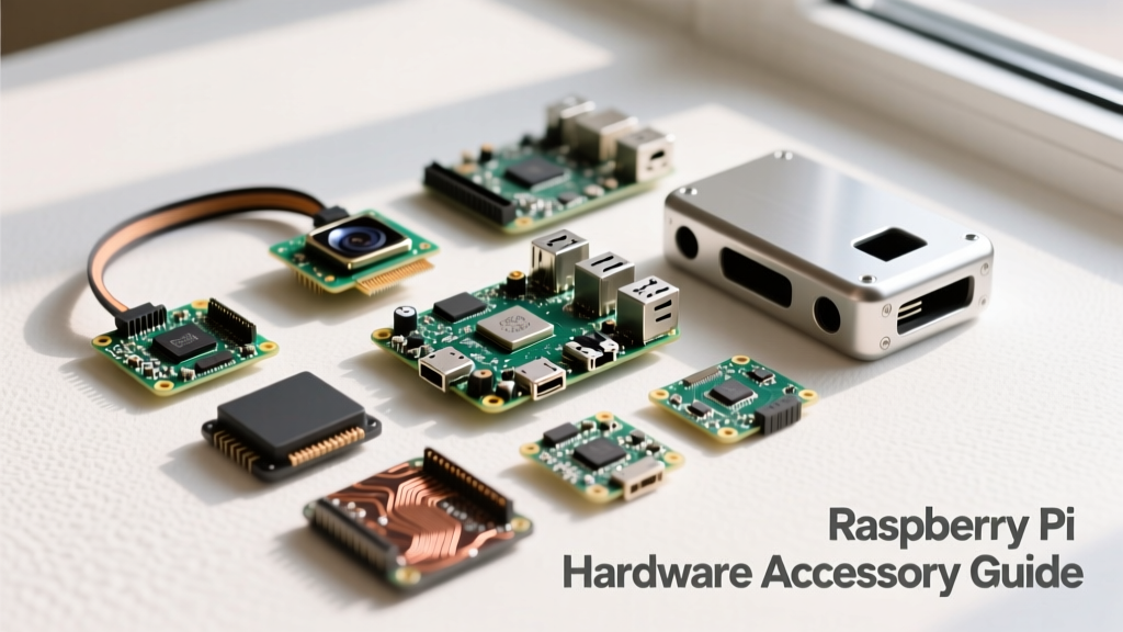
To truly evaluate a pinout, we must test it with the hardware designed to exploit it. Here is our review of three popular accessories and how they interact with the Pi 3's specific architecture.
1. Adafruit Capacitive Touch HAT (I2C Mapping)
The Adafruit Capacitive Touch HAT is a staple for kiosk and interactive projects. It communicates via the primary I2C bus (Pins 3 and 5). However, its brilliance lies in its use of BCM 4 (Pin 7) as a dedicated IRQ (Interrupt Request) line. Instead of polling the I2C bus continuously—which wastes CPU cycles—the Pi 3 only reads touch data when Pin 7 is pulled low. Reviewer Note: Because the Pi 3's I2C1 bus already has 1.8kΩ pull-ups, ensure you do not stack another HAT with aggressive 1kΩ pull-ups, or the signal rise times will degrade, causing touch ghosting.
2. RasPiO Analog Zero (SPI & MCP3008)
The Raspberry Pi lacks a native Analog-to-Digital Converter (ADC). The RasPiO Analog Zero solves this by integrating an MCP3008 10-bit ADC chip. It maps directly to the SPI0 interface (Pins 19, 21, 23, and 24). In our bench tests, the Pi 3's SPI clock can comfortably sustain 1.2 MHz, allowing for rapid sampling of potentiometers and analog gas sensors. The physical footprint of this board is exceptionally slim, leaving enough clearance above the Pi 3's Ethernet port for standard ribbon cables.
3. PiJuice HAT (Power Management & Wake-up)
The PiJuice is a UPS and power management HAT that fundamentally changes how the Pi 3 operates. While it uses I2C for battery telemetry, its most critical pinout interaction is with Pin 5 (BCM 3 / SCL). The Pi 3 can be configured to wake from a halted state when Pin 5 is pulled low. The PiJuice's onboard RTC (Real Time Clock) triggers this exact pin to power on the Pi 3 for scheduled data-logging tasks. According to the PiJuice GitHub Repository, this requires specific daemon configurations, but the hardware mapping on the Pi 3 is flawlessly reliable.
Critical Troubleshooting: UART Conflicts and Voltage Traps
Reviewing the pinout for Raspberry Pi 3 would be incomplete without addressing the notorious hardware quirks introduced in this specific generation. If you are connecting serial accessories (like GPS modules or Zigbee coordinators), you will likely encounter the UART/Bluetooth conflict.
The Bluetooth / Mini-UART Swap
On the Pi 1 and 2, Pins 8 and 10 (BCM 14/15) were mapped to the primary hardware UART (/dev/ttyAMA0), which featured a robust FIFO buffer and stable baud rates. On the Pi 3, Raspberry Pi reassigned /dev/ttyAMA0 to the onboard Bluetooth module. Pins 8 and 10 were relegated to the 'mini-UART' (/dev/ttyS0), which lacks flow control and ties its baud rate to the VPU core clock. If your Pi 3 CPU throttles, your serial accessory will receive corrupted data.
The Fix: You must force the Bluetooth module back to the mini-UART. Add the following line to your /boot/config.txt file:
dtoverlay=pi3-miniuart-btThis restores the stable hardware UART to Pins 8 and 10, a mandatory step for any reliable serial accessory on the Pi 3.
Physical Clearance on the Pi 3B+
If you are upgrading from a Pi 3B to a 3B+, be aware of the 4-pin PoE (Power over Ethernet) header added to the top right of the board. While not part of the main 40-pin pinout for Raspberry Pi 3, many older, poorly designed HATs with overhanging components or unshielded undersides will physically short against these exposed PoE pins. Always use the included M2.5 standoff spacers when mounting HATs on a Pi 3B+ to prevent catastrophic short circuits.
Final Verdict on the Pi 3 GPIO Ecosystem
The 40-pin header on the Raspberry Pi 3 remains a masterclass in accessible hardware design, balancing high-speed SPI, multi-drop I2C, and versatile GPIOs in a compact footprint. However, it demands respect for its electrical limits—specifically the 50mA 3.3V constraint and the UART routing quirks. By understanding the deep-level mappings detailed in this review, and referencing the official Raspberry Pi hardware documentation, you can confidently design, troubleshoot, and deploy complex accessory stacks without frying your board or corrupting your data.