
The Evolution of DIY Robotics: Moving Beyond the L298N
When searching for Arduino projects ideas, most online tutorials cap out at basic obstacle-avoiding cars utilizing HC-SR04 ultrasonic sensors and L298N H-bridge motor drivers. While excellent for learning basic Boolean logic, these legacy components lack the torque, precision, and processing overhead required for modern robotics. In 2026, the DIY robotics landscape has matured significantly. With the advent of dual-core microcontrollers, closed-loop stepper systems, and accessible SLAM (Simultaneous Localization and Mapping) algorithms, hobbyists can now engineer machines that rival entry-level industrial platforms.
This guide explores advanced Arduino projects ideas tailored for serious robotics builds, focusing on kinematics, sensor fusion, and robust power architectures that prevent catastrophic brownouts.
3 High-Impact Arduino Projects Ideas for Serious Builders
1. Autonomous SLAM Rover with ROS 2 Integration
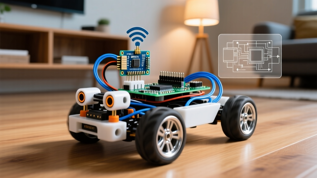
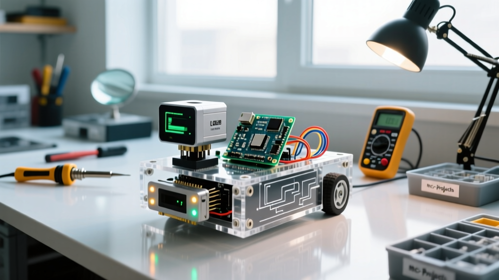
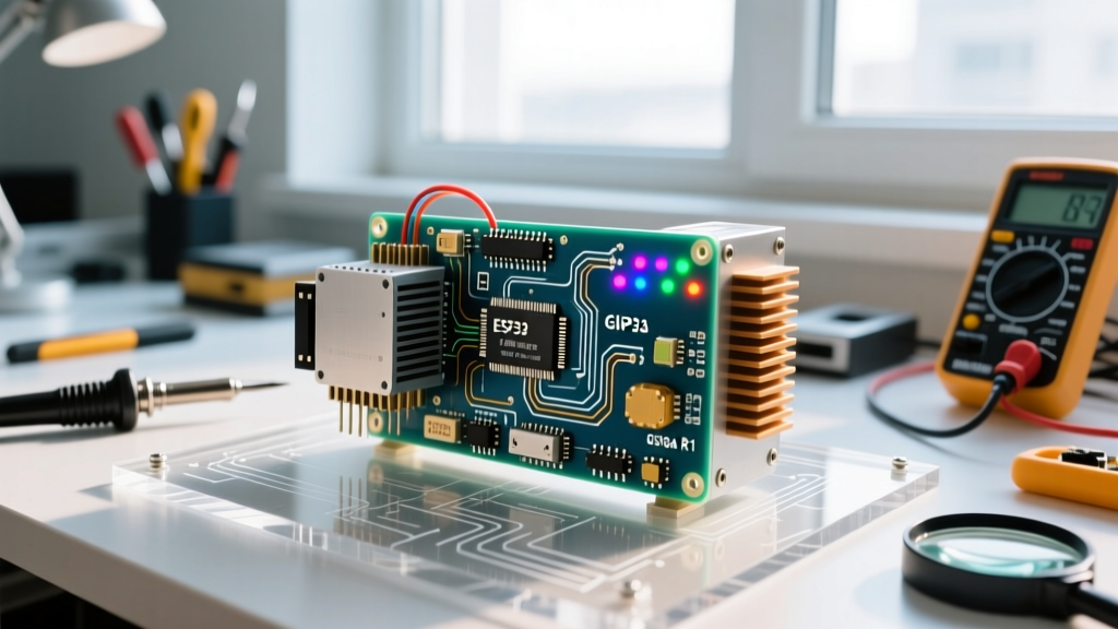
The ultimate test of a mobile robot is autonomous navigation in unmapped environments. By pairing the Arduino GIGA R1 WiFi (featuring a dual-core STM32H747XI) with an RPLiDAR A1M8, you can build a rover capable of generating real-time 2D occupancy grids.
- Compute Architecture: Use the GIGA's M7 core for high-level path planning and the M4 core for real-time motor PID control.
- Software Stack: Implement Micro-ROS via ROS 2 Humble to bridge the Arduino ecosystem with professional robotics middleware.
- Drive System: Replace standard DC gear motors with NEMA 17 stepper motors equipped with planetary gearboxes (50:1 ratio) for precise odometry without wheel slip.
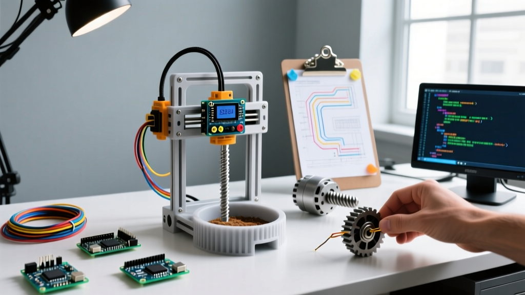
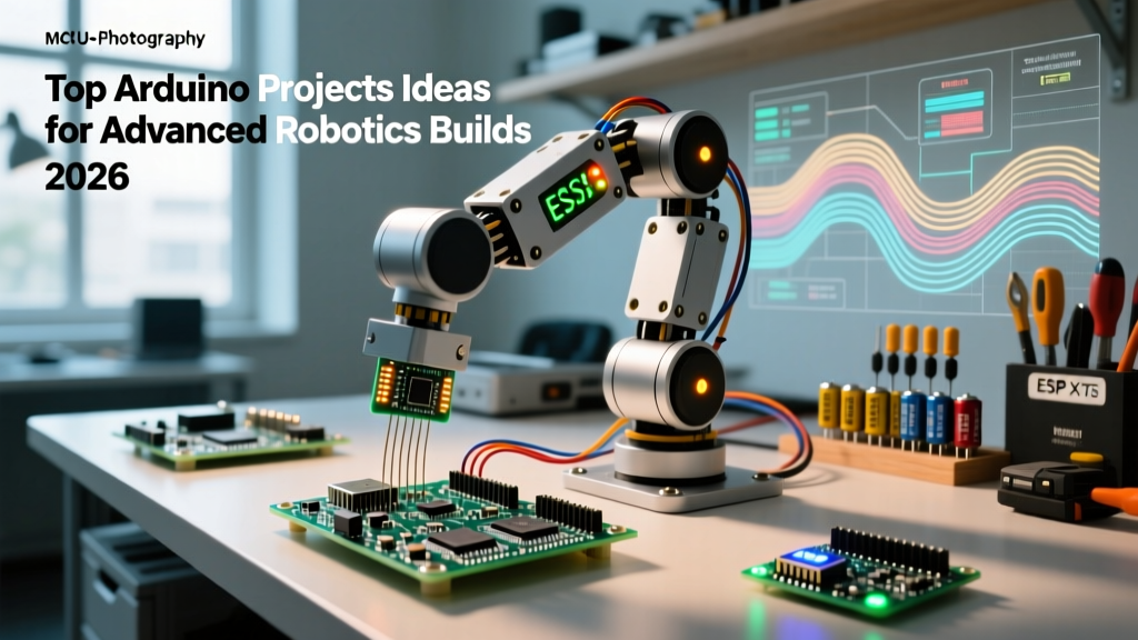
2. 6-DOF Palletizing Robotic Arm via Inverse Kinematics
Standard servo-based robotic arms suffer from gear backlash and poor payload capacity. For a 2026 industrial-style build, utilize the Teensy 4.1 (programmable via the Arduino IDE) to handle complex floating-point inverse kinematics calculations at 600 MHz.
Instead of open-loop NEMA steppers which silently drop steps under heavy loads, integrate iHSV57 closed-loop stepper motors. These feature built-in magnetic encoders that provide real-time position feedback over RS485 or CAN bus, ensuring the arm never loses its zero-position calibration, even if physically forced out of bounds.
3. Active Suspension Self-Balancing Payload Carrier
Self-balancing robots are a classic rite of passage, but adding an active suspension layer for payload stabilization elevates the project to professional tiers. Using a BNO086 9-DOF IMU, you can leverage onboard sensor fusion to output clean quaternion data at 400Hz, bypassing the noisy raw accelerometer data that plagues older MPU6050 setups.
Expert Tip: When tuning the cascaded PID loops for balancing, tune the inner rate loop first (targeting 1kHz update rate), then the outer angle loop (targeting 200Hz). Attempting to tune both simultaneously will result in violent oscillations and destroyed gearboxes.
Component Selection Matrix for 2026 Robotics Builds
Upgrading your bill of materials is the fastest way to eliminate mechanical and electrical headaches. Below is a comparison matrix contrasting legacy beginner components with modern advanced alternatives.
| Subsystem | Legacy / Beginner Component | 2026 Advanced Alternative | Estimated Cost |
|---|---|---|---|
| Motor Control | L298N H-Bridge | ODrive S1 or Cytron MD30C | $85 - $135 |
| Microcontroller | Arduino Uno R3 (ATmega328P) | Arduino GIGA R1 WiFi or Teensy 4.1 | $32 - $75 |
| Spatial Tracking | MPU6050 (Raw I2C) | BNO086 (SPI / Sensor Hub) | $25 - $40 |
| Power Regulation | LM2596 Buck Converter | TPS5430 Synchronous Buck | $3 - $8 |
Power Architecture: The Most Common Point of Failure
The number one reason advanced robotics projects fail during testing is inadequate power distribution. When a high-torque motor stalls or rapidly reverses direction, it generates massive inductive voltage spikes and draws instantaneous current spikes that can exceed 20A. If your logic and motor circuits share a common, unregulated ground plane, these spikes will induce brownouts, resetting your Arduino mid-operation and potentially corrupting the EEPROM.
Designing a Split-Rail Power System
- Primary Source: Use a 4S LiFePO4 battery pack (12.8V nominal). Unlike LiPo batteries, LiFePO4 offers a flatter discharge curve and vastly superior cycle life (2000+ cycles), making it ideal for robots that undergo daily testing.
- Motor Rail: Feed the raw battery voltage directly to your motor controllers (e.g., ODrive S1), ensuring you use braided copper wiring (12 AWG minimum) to minimize resistance and voltage sag.
- Logic Rail: Use a TPS5430 synchronous buck converter to step down the 12.8V to a clean 5V/3A rail for the Arduino and sensors. Avoid the ubiquitous LM2596 modules; they suffer from high quiescent current, poor thermal efficiency at low loads, and cheap counterfeit inductors that fail under sustained 2A draws.
- Isolation: Implement digital isolators like the ISO7721 on serial communication lines (UART/CAN) between the motor controllers and the Arduino to completely sever ground loops.
- Protection: Place a bidirectional TVS diode (e.g., 1.5KE15CA) directly across the main battery terminals to clamp inductive kickback. Additionally, solder a bank of low-ESR electrolytic capacitors (minimum 2200µF, 25V rated) as close to the motor driver power inputs as possible to act as a local energy reservoir during rapid acceleration.
Sensor Fusion and I2C Edge Cases
As your robot grows, you will inevitably daisy-chain multiple sensors (LiDAR, IMUs, ToF distance sensors, environmental monitors) onto the I2C bus. The official Arduino I2C documentation and the I2C specification dictate a maximum bus capacitance of 400pF. In a large robot chassis with long, unshielded ribbon cables, trace and wire capacitance can easily exceed this limit, resulting in corrupted data packets and bus lockups.
The Solution: Do not rely on internal pull-up resistors. Use an active I2C multiplexer like the TCA9548A to split the bus into isolated channels, effectively resetting the capacitance limit per channel. Alternatively, migrate high-bandwidth sensors (like the BNO086 IMU) to the SPI bus, which is immune to capacitance-induced clock stretching issues.
Frequently Asked Questions
Can standard 8-bit Arduino boards handle real-time kinematics?
While an ATmega2560 can handle basic differential drive kinematics, calculating 6-DOF inverse kinematics requires heavy floating-point math. 8-bit AVRs lack a hardware Floating Point Unit (FPU), forcing the compiler to use slow software emulation. For robotic arms or multi-legged walkers, upgrading to a 32-bit ARM Cortex-M7 board (like the Teensy 4.1 or Arduino GIGA) is mandatory to maintain a control loop frequency above 500Hz.
How do I prevent wheel slip from ruining my odometry?
Wheel slip is the enemy of dead-reckoning. To mitigate this, implement sensor fusion by combining wheel encoder data with an IMU using an Extended Kalman Filter (EKF). Furthermore, utilize high-quality motor controllers that support current-sense feedback; a sudden spike in motor current without a corresponding change in encoder ticks is a reliable indicator of wheel slip or a physical collision.
Should I use CAN bus instead of UART for motor control?
Absolutely. UART is highly susceptible to electromagnetic interference (EMI) generated by brushless and brushed motors. CAN bus (using transceivers like the MCP2551) utilizes differential signaling, making it virtually immune to the noisy electrical environment of a robotics chassis. It also allows you to daisy-chain multiple motor controllers and smart servos on a single twisted-pair cable, drastically reducing wiring harness weight and complexity.