
Why the LCD Arduino 16x2 Remains an Industrial Staple in 2026
While high-resolution OLEDs and IPS TFT displays dominate modern consumer electronics, the classic LCD Arduino 16x2 module remains a cornerstone of real-world industrial control panels, greenhouse monitors, and ruggedized IoT dashboards. The reasoning is purely practical: extreme readability in direct sunlight, negligible power draw (under 2mA with the backlight disabled), and bulletproof electrical resilience. When building a remote environmental monitoring node powered by a 12V solar lead-acid battery, a 16x2 LCD outperforms fragile glass OLEDs that suffer from burn-in when displaying static sensor telemetry for months on end.
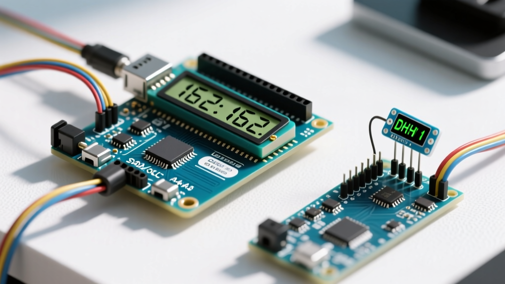
In this guide, we will move beyond basic "Hello World" tutorials and engineer a robust, real-world environmental dashboard. We will integrate a Bosch BME280 environmental sensor with an I2C-equipped 16x2 LCD, addressing the critical hardware physics, logic-level shifting, and code optimizations required for a deployment-ready system.
Hardware Architecture: Parallel vs. I2C Backpacks
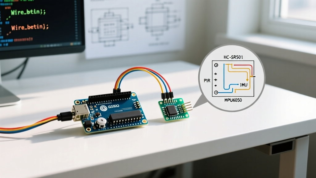
The ubiquitous 16x2 LCD is driven by the Hitachi HD44780U controller (or modern equivalents like the SPLC780D). Out of the box, these displays require a 16-pin parallel interface, consuming six digital I/O pins on your microcontroller just to operate in 4-bit mode. In real-world applications where I/O pins are at a premium, engineers solder a PCF8574 I2C backpack to the rear of the display.
According to the Texas Instruments PCF8574 Datasheet, this I/O expander translates I2C serial commands into the parallel signals required by the HD44780, reducing the microcontroller connection to just four wires (VCC, GND, SDA, SCL).
| Feature | Raw 16-Pin Parallel | PCF8574 I2C Backpack |
|---|---|---|
| Microcontroller Pins Used | 6 Digital I/O (RS, EN, D4-D7) | 2 Pins (SDA, SCL) |
| Contrast Adjustment | Requires external 10kΩ Potentiometer | Integrated Trimpot on backpack |
| Backlight Control | Requires NPN Transistor + PWM Pin | Hardware Jumper or I2C Command |
| Wiring Complexity | High (Prone to breadboard noise) | Low (Daisy-chainable I2C bus) |
Real-World Build: Greenhouse Climate Dashboard
For our application, we are building a localized climate node for a commercial hydroponics facility. The system must read temperature and humidity and display it continuously without flickering.
Component List & 2026 Pricing
- Microcontroller: Arduino Nano 33 IoT ($18.00) - Chosen for its native 3.3V logic and Wi-Fi capabilities.
- Display: 16x2 Character LCD with PCF8574T I2C Backpack ($4.50 - $6.00).
- Sensor: Bosch BME280 Breakout Board ($9.00 - $12.00). As noted on the Bosch Sensortec BME280 Product Page, this sensor provides superior humidity stability compared to cheaper DHT22 alternatives.
- Logic Level Shifter: BSS138 Bidirectional MOSFET Module ($2.00).
Circuit Schematic & The 3.3V vs 5V Logic Trap
A critical failure mode in modern IoT builds is mixing 3.3V microcontrollers with 5V I2C peripherals. The HD44780 LCD and standard PCF8574 backpacks require 5V for proper contrast and backlight illumination. However, feeding 5V back into the 3.3V SDA/SCL pins of an Arduino Nano 33 IoT will degrade the silicon over time.
Expert Rule: Never rely solely on the internal pull-up resistors of a 3.3V microcontroller when communicating with a 5V I2C backpack. Always use a bidirectional logic level shifter (like the BSS138) to translate the 3.3V I2C signals to 5V, ensuring clean edge transitions and protecting your MCU.
Wiring Matrix:
- BME280 (3.3V side): VIN to 3.3V, GND to GND, SDA to Nano SDA, SCL to Nano SCL.
- LCD I2C Backpack (5V side): VCC to 5V, GND to GND, SDA to Level Shifter HV1, SCL to Level Shifter HV2.
- Pull-up Resistors: Ensure 4.7kΩ pull-up resistors are present on the 5V I2C lines. Most cheap backpacks omit these, leading to bus hangs in electrically noisy greenhouse environments.
Optimized C++ Implementation
When displaying real-time sensor data, calling lcd.clear() in the main loop is a rookie mistake. The clear command takes approximately 1.5ms to execute and causes a visible, annoying flicker on the screen. Instead, we use precise cursor positioning and space-padding to overwrite stale data. Below is the optimized implementation utilizing the Arduino LiquidCrystal I2C Reference Library.
#include <Wire.h>
#include <LiquidCrystal_I2C.h>
#include <Adafruit_BME280.h>

// Initialize I2C address 0x27, 16 columns, 2 rows
LiquidCrystal_I2C lcd(0x27, 16, 2);
Adafruit_BME280 bme;

void setup() {
  Wire.begin();
  lcd.init();
  lcd.backlight();

  if (!bme.begin(0x76)) {
    lcd.print("BME280 Fail!");
    while (1); // Halt on critical sensor failure
  }

  // Static UI elements written only once
  lcd.setCursor(0, 0);
  lcd.print("Temp: ");
  lcd.setCursor(0, 1);
  lcd.print("Hum:  ");
}

void loop() {
  float temp = bme.readTemperature();
  float hum = bme.readHumidity();

  // Dynamic Data Overwrite (No Flicker)
  lcd.setCursor(6, 0);
  lcd.print(temp, 1); // 1 decimal place
  lcd.print((char)223); // Degree symbol
  lcd.print("C   "); // Padding to overwrite old digits

  lcd.setCursor(6, 1);
  lcd.print(hum, 1);
  lcd.print("%   ");

  delay(2000); // 2-second polling rate
}
Advanced Troubleshooting & Edge Cases
Deploying an LCD Arduino 16x2 in the field introduces environmental and electrical variables that bench testing often misses. Here is how to diagnose the most common real-world anomalies.
1. The "Black Boxes" Contrast Issue
If your display powers on but only shows a row of solid black blocks on the top line, the contrast voltage (V0) is incorrect. On I2C backpacks, this is controlled by the small blue trimpot. Fix: Use a small Phillips screwdriver to turn the trimpot counter-clockwise until the characters become crisp. Note that LCD contrast shifts with ambient temperature; a display tuned in a 20°C lab may become unreadable in a 35°C greenhouse. For extreme environments, wire a thermistor to the contrast pin to auto-compensate.
2. I2C Address Conflicts (0x27 vs 0x3F)
Manufacturers use two different I/O expander chips for backpacks: the PCF8574T and the PCF8574AT. While functionally identical, their base I2C addresses differ. The 'T' variant defaults to 0x27, while the 'AT' variant defaults to 0x3F. If your code compiles but the screen remains blank, run an I2C Scanner sketch to verify the physical address of your specific module.
3. Ghosting and Bus Capacitance
If you are running long CAT5e cables to remote sensors, the I2C bus capacitance will exceed the 400pF limit specified in the I2C standard. This results in rounded signal edges, causing the LCD to display random "ghost" characters or freeze entirely. Fix: Lower the I2C pull-up resistors from 4.7kΩ to 2.2kΩ to provide a stronger current source, or integrate an active I2C bus extender IC like the P82B715 for runs exceeding 2 meters.
Conclusion
The LCD Arduino 16x2 is far from obsolete. By pairing it with modern I2C environmental sensors and respecting the underlying electrical physics of bus capacitance and logic-level translation, engineers can build highly reliable, low-power telemetry dashboards that survive the rigors of real-world industrial and agricultural deployments.