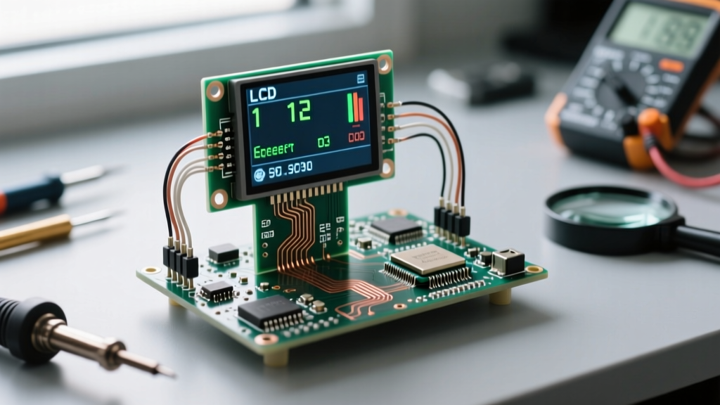

The 16x2 and 20x4 character LCDs equipped with an I2C backpack are arguably the most ubiquitous peripherals in the microcontroller ecosystem. For hobbyists, they offer a painless way to display sensor readings without sacrificing a dozen GPIO pins. However, when transitioning from a controlled breadboard environment to a real-world sensor dashboard—such as an outdoor weather station, a greenhouse climate monitor, or an industrial machine readout—the standard approach often falls apart. Signal degradation, address collisions, and library incompatibilities can turn a simple integration into a week-long debugging nightmare.
In this guide, we bypass the basic 'Hello World' tutorials and dive deep into the electrical and firmware realities of deploying an LCD display I2C module in production-grade microcontroller projects. We will cover bus capacitance management, PCF8574 address mapping, and the definitive firmware choices for 2026 and beyond.
The Reality of I2C LCDs in Field Deployments
When engineers design a custom PCB or wire a permanent enclosure for an environmental sensor node, the physical layer of the I2C bus becomes the primary point of failure. The I2C protocol was designed for short-distance, on-board communication between integrated circuits. It is not inherently suited for long ribbon cables running through electrically noisy environments.
A standard LCD display I2C backpack draws roughly 20mA to 60mA depending on the backlight status. If you are powering a 20x4 LCD alongside a suite of I2C sensors (like BME280 or SHT31) on a shared 5V rail, voltage sag can cause the LCD controller to brownout during initialization. Furthermore, the mechanical contrast trimpot (a 10k ohm variable resistor) found on the back of the I2C backpack is highly susceptible to temperature drift. In an outdoor enclosure experiencing a 30°C daily temperature swing, a contrast setting calibrated at dawn may render the display completely illegible by mid-afternoon. Replacing this mechanical pot with a fixed resistor voltage divider or a digital potentiometer is a common necessity for ruggedized dashboards.
Anatomy of the PCF8574 Backpack and Address Conflicts
The vast majority of I2C LCD backpacks utilize the NXP (or Texas Instruments) PCF8574 8-bit I/O expander. This chip translates the I2C serial data into the parallel signals required by the Hitachi HD44780 LCD controller. However, a massive source of confusion in real-world deployments stems from the existence of two nearly identical chips: the PCF8574 and the PCF8574A.
According to the TI PCF8574 datasheet, the base PCF8574 chip has a hardcoded base address of 0x20, while the PCF8574A variant has a base address of 0x38. The three address pins (A0, A1, A2) on the backpack allow for 8 permutations per chip.
| Jumper State (A0, A1, A2) | PCF8574 Address | PCF8574A Address |
|---|---|---|
| Open, Open, Open (Default) | 0x27 | 0x3F |
| Closed, Open, Open | 0x26 | 0x3E |
| Open, Closed, Open | 0x25 | 0x3D |
| Closed, Closed, Open | 0x24 | 0x3C |
If you are building a dashboard with multiple I2C devices, you must physically bridge the address pads on the PCB with solder to shift the LCD away from conflicting addresses. Always run an I2C scanner sketch before finalizing your enclosure wiring to verify the exact hex address of your specific backpack batch.
Hardware Wiring: Managing Capacitance and Pull-Ups
The most critical mistake made when wiring an LCD display I2C setup over distances greater than 20 centimeters is ignoring bus capacitance. The I2C specification mandates a maximum bus capacitance of 400pF. Long ribbon cables, especially those running parallel to AC mains or PWM motor drivers, introduce parasitic capacitance and electromagnetic interference (EMI).
Most cheap I2C backpacks include 10k ohm surface-mount pull-up resistors on the SDA and SCL lines. As detailed in SparkFun's comprehensive I2C tutorial, 10k pull-ups are generally too weak to pull the bus high quickly enough when capacitance increases, resulting in rounded signal edges that the microcontroller misinterprets as data corruption.
The Pull-Up Resistor Fix
If your I2C LCD is dropping characters or freezing when connected via a 30cm+ cable, you must strengthen the pull-ups. Soldering an additional 4.7k ohm or 2.2k ohm through-hole resistor between the SDA/SCL lines and the 5V VCC pin at the microcontroller end will drastically sharpen the rising edges of your I2C signals. For highly noisy environments, such as near stepper motor drivers, route your SDA and SCL wires as a twisted pair to maximize common-mode noise rejection.
Firmware Showdown: LiquidCrystal_I2C vs. hd44780
For years, the default choice for Arduino developers was the 'LiquidCrystal_I2C' library by Frank de Brabander. While functional, it suffers from a major architectural flaw: it requires the developer to manually map the PCF8574 output pins to the HD44780 LCD pins in the constructor. Because different manufacturers wire the backpacks differently (e.g., En, Rw, Rs, D4-D7 mapping varies wildly), developers frequently end up with a blank screen simply because the hardcoded pinmap in the sketch doesn't match the physical PCB traces of their specific $3 eBay module.
The modern, professional standard is the hd44780 library by Bill Perry. This library is a masterclass in embedded software design. Instead of guessing pinmaps, the hd44780 library's 'hd44780_I2Cexp' class automatically scans the I2C bus, identifies the backpack address, and uses a built-in diagnostic algorithm to deduce the exact pin mapping by toggling bits and reading the LCD's internal busy flag.
Implementation Strategy
When writing firmware for a permanent sensor dashboard, always use the hd44780 library. It includes built-in methods for handling I2C bus timeouts, ensuring that if the LCD temporarily disconnects due to a physical bump or voltage sag, the microcontroller's main loop won't hang indefinitely waiting for an I2C ACKnowledge (ACK) bit that will never arrive.
Real-World Troubleshooting Matrix
When deploying these displays in the field, use this diagnostic matrix to quickly identify and resolve hardware and firmware anomalies.
| Symptom | Root Cause | Engineering Fix |
|---|---|---|
| Top row shows solid black boxes | LCD controller failed to initialize; 4-bit mode handshake failed. | Check 5V rail stability; add 100uF decoupling capacitor near VCC pin. |
| Display works, but random characters appear | I2C bus noise; SDA/SCL signal edge degradation. | Reduce pull-up resistance to 2.2k; use twisted pair wiring. |
| Backlight is on, but no text is visible | Contrast voltage (V0) is out of spec for current temperature. | Adjust trimpot; for permanent fix, replace pot with fixed 1k/2.2k voltage divider. |
| Microcontroller freezes randomly | I2C bus lockup; missing pull-ups or cable disconnected. | Enable internal microcontroller pull-ups as fallback; implement I2C watchdog timer. |
Field Engineer Tip: Notice the jumper on the I2C backpack labeled 'LED'? This jumper connects the LCD backlight LED anode directly to the 5V VCC pin through a small current-limiting resistor (usually 10 ohms). If you are running a low-power battery-operated sensor node, remove this jumper and wire the backlight to a MOSFET controlled by a microcontroller GPIO. This allows you to completely cut power to the backlight when the dashboard is idle, reducing the module's current draw from ~60mA down to less than 2mA.
By respecting the electrical limitations of the I2C bus, verifying your specific PCF8574 address mapping, and leveraging auto-discovery firmware, the humble 1602 and 2004 LCDs remain incredibly reliable, cost-effective interfaces for real-world sensor dashboards.