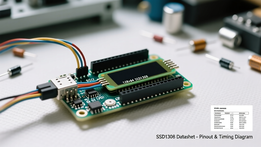

The Gap Between Datasheet and Reality: SSD1306 Modules
When you purchase a generic 0.96-inch Arduino OLED display online, you are almost certainly buying a module built around the Solomon Systech SSD1306 controller IC. While the official SSD1306 datasheet is a comprehensive 67-page document detailing everything from oscillator circuits to SPI timing diagrams, it rarely tells you how to actually wire the cheap breakout board sitting on your desk.
As a hardware integrator, relying solely on copy-pasted library code is a recipe for mysterious I2C bus hangs, fried logic pins, and memory crashes. This datasheet explainer bridges the gap between the raw silicon specifications and real-world Arduino integration, focusing on the critical hardware quirks that tutorials often ignore.
Memory Architecture: GDDRAM and the SRAM Trap
To understand why your Arduino sketch might crash when using an OLED, you must understand the Graphics Display Data RAM (GDDRAM). The SSD1306 does not possess its own high-level rendering engine; it relies on a 1024-byte (1KB) GDDRAM buffer to map pixels to the physical screen.
Page Addressing Explained
The 128x64 pixel display is divided into 8 horizontal 'pages', each containing 8 rows of pixels (128 columns x 8 rows = 1024 bytes). Every byte in the GDDRAM represents a vertical column of 8 pixels. If you want to turn on the top-left pixel, you write a '1' to the least significant bit of the first byte in Page 0.
Expert Insight: Because the SSD1306 lacks an internal frame buffer accessible via simple X/Y coordinates, libraries like Adafruit GFX allocate a 1KB buffer in your microcontroller's SRAM. On an ATmega328P (Arduino Uno/Nano) with only 2KB of total SRAM, the OLED display consumes 50% of your available memory before your own variables are even declared. For complex projects, consider switching to an ESP32 or using a partial-buffer library like U8g2.
Decoding the Pinout: I2C vs. SPI Configurations
Most hobbyist Arduino OLED displays utilize a 4-pin I2C interface (GND, VCC, SCL, SDA). However, the datasheet reveals a critical detail about the I2C bus that cheap module manufacturers frequently mishandle: pull-up resistors.
The Hidden Pull-Up Resistor Trap
The I2C specification requires pull-up resistors on the SDA and SCL lines. According to the NXP I2C Bus Specification, these resistors pull the bus voltage to VCC. Here lies the hardware trap:
- The 5V Pull-Up Error: Many mass-produced OLED modules place 4.7kΩ pull-up resistors tied directly to the 5V VCC pin. If you connect this module to a 3.3V microcontroller (like an ESP32 or Arduino Due), the 5V pull-ups will backfeed 5V into your MCU's 3.3V I2C pins, potentially destroying the silicon over time.
- Missing Pull-Ups: Conversely, some ultra-cheap clones omit the resistors entirely to save fractions of a cent. This results in floating I2C lines, causing the Arduino Wire library to hang indefinitely during a bus scan.
Verification Step: Always use a multimeter to measure the resistance between the SDA/SCL pins and VCC on your specific module before connecting it to a 3.3V logic board.
Logic Level Translation: The 5V Arduino Danger Zone
The SSD1306 datasheet specifies that the logic interface voltage (VDDIO) must match the I/O voltage of the MCU. The core logic operates internally at roughly 2.8V to 3.3V. Let us look at how different microcontrollers interact with the display's logic thresholds.
| Microcontroller | Logic Level | SSD1306 VDDIO Tolerance | Integration Strategy |
|---|---|---|---|
| ATmega328P (Uno) | 5.0V | Max 3.6V (Absolute Max) | Requires logic level shifter or 3.3V Pro Mini |
| ESP32 / ESP8266 | 3.3V | Native Match | Direct connection safe (watch for 5V pull-ups) |
| Arduino Nano 33 IoT | 3.3V | Native Match | Direct connection safe |
| Raspberry Pi Pico | 3.3V | Native Match | Direct connection safe |
While the absolute maximum rating for VDDIO is 3.6V, thousands of makers connect 5V Arduinos directly to these OLEDs without immediate failure. Why? Because the internal protection diodes on the SSD1306 clamp the excess voltage. However, this causes continuous current leakage, thermal degradation, and drastically reduces the lifespan of the display IC. For professional or long-term deployments, a bidirectional logic level shifter (like the BSS138) is mandatory for 5V MCUs.
The Internal Charge Pump: A Datasheet Secret
OLED pixels require a high voltage (typically 7V to 12V) to illuminate the organic diodes, despite the logic running at 3.3V. The SSD1306 datasheet outlines two power supply modes:
- External VCC: You supply the 7V-12V directly to the VCC pin (rare on hobby modules).
- Internal Charge Pump: The IC generates the high voltage internally from a 3.3V logic supply using external capacitors.
Almost all 4-pin I2C Arduino OLED modules rely on the internal charge pump. If your display is wired perfectly, the I2C scan succeeds, but the screen remains completely black, the charge pump has not been enabled in software.
Crucial Initialization Hex Commands
To activate the internal charge pump, your initialization sequence must send the following byte sequence over I2C:
0x8D(Charge Pump Setting Command)0x14(Enable Charge Pump)
If you are writing a bare-metal driver without a library, forgetting the 0x14 payload is the number one cause of 'black screen' failures. Following this, you must send 0xAF to turn the display output ON.
Real-World Failure Modes and Troubleshooting
Even with perfect wiring, environmental and manufacturing variances cause distinct failure modes. Here is how to diagnose them using datasheet principles.
1. The 'Snow' or White Noise Screen
Symptom: The screen fills with random static or white noise upon boot.
Cause: This is an initialization race condition. The SSD1306 requires a stable power rail before the RESET pin is pulled high. If your Arduino toggles the I2C lines before the OLED's internal voltage regulator has stabilized, the GDDRAM fills with garbage data.
Fix: Add a 100ms delay in your setup() function before calling display.begin(), or wire the OLED's RESET pin to a GPIO and manually pulse it LOW for 10ms, then HIGH.
2. I2C Address Conflicts (0x3C vs 0x3D)
Symptom: The I2C scanner sketch finds no devices, or finds the wrong device.
Cause: The datasheet states the slave address is determined by the SA0 pin. If SA0 is tied to GND, the 7-bit address is 0x3C. If tied to VCC, it is 0x3D. Some manufacturers flip this wiring without updating the silkscreen.
Fix: Always run an I2C scanner sketch first. If you need two OLEDs on one bus, you must physically desolder and move the tiny 0402 SA0 resistor on the back of one module.
3. The SH1106 Clone Imposter
Symptom: Your code works, but the image is shifted 4 pixels to the right, or the edges wrap around.
Cause: You did not buy an SSD1306. You bought a module with a SH1106 controller. The SH1106 is a clone that manages a 132x64 GDDRAM but only displays 128x64. It lacks the internal charge pump commands and uses a different memory paging sequence.
Fix: Inspect the tiny black IC under a magnifying glass. If it reads SH1106, you must switch your Arduino library (e.g., use the 'U8g2' library and select the SH1106 constructor) to handle the 4-pixel column offset.
Summary for Hardware Designers
Integrating an Arduino OLED display goes far beyond plugging four wires into a breadboard. By understanding the GDDRAM page architecture, respecting the 3.3V logic thresholds, and mastering the charge pump initialization commands, you transition from a sketch-copier to a competent embedded systems engineer. Always verify your module's pull-up resistor configuration and logic levels before applying power to ensure your microcontroller survives the integration process.