
The FPC Connector & OV2640 Hardware Trap
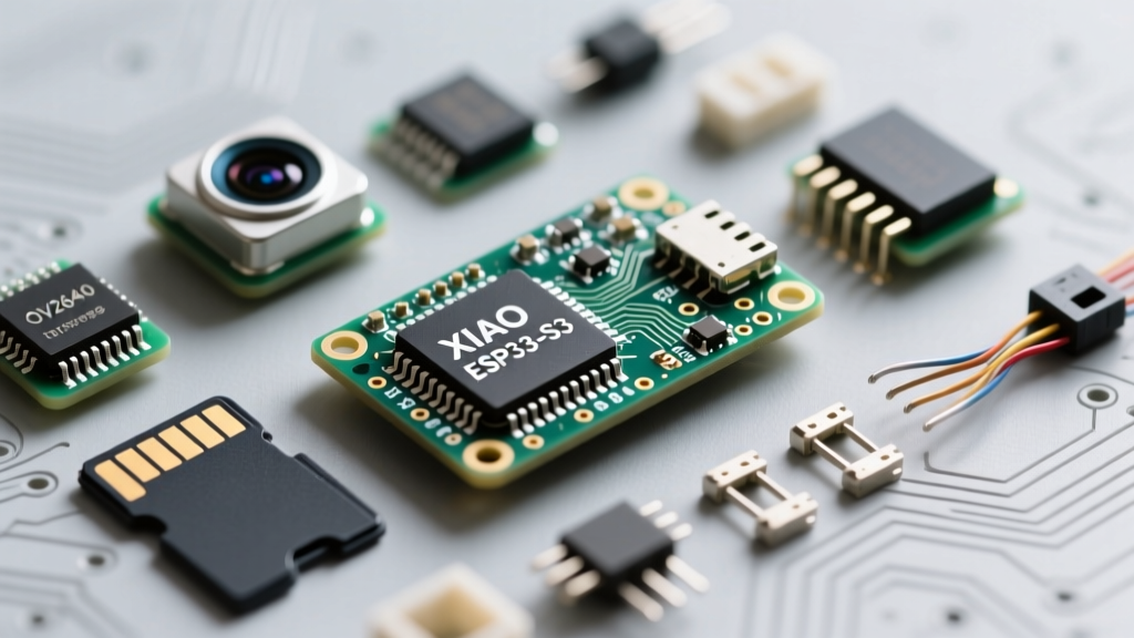
The Seeed Studio XIAO ESP32-S3 Sense is a marvel of miniaturization, packing an ESP32-S3, an OV2640 camera, and a microSD slot into a 21x17.5mm footprint. However, its dense layout introduces unique hardware failure modes that standard Arduino troubleshooting guides completely ignore. The most frequent point of failure is the physical connection between the main SoC board and the camera/sensor expansion board.
The OV2640 camera module connects via a 0.5mm pitch FPC (Flexible Printed Circuit) ribbon cable. A massive real-world failure mode occurs when makers attempt to reseat this cable. The FPC connector on the Sense expansion board utilizes a flip-up latch, not a slide-out friction lock. If you pull the cable without flipping the black plastic latch up 90 degrees, you will shear the microscopic solder pads off the PCB. If your serial monitor outputs Camera init failed with error 0x105 or 0x20001 immediately upon boot, the ribbon cable is either seated backward, the latch is broken, or the gold contacts are oxidized. Always clean the ribbon contacts with 99% isopropyl alcohol before reseating, and ensure the blue stiffener backing faces the correct direction as outlined in the Seeed Studio XIAO ESP32S3 Wiki.
Breaking the Boot & Upload Deadlock
Unlike larger ESP32 dev boards, the XIAO series lacks a robust auto-reset DTR/RTS circuit on many third-party carrier boards. This results in an upload deadlock where the Arduino IDE times out waiting for the bootloader to respond, displaying Failed to connect to ESP32-S3: No serial data was received.
To force the ESP32-S3 into UART download mode, you must manually bridge GPIO0 to GND during the reset sequence. If you are using the official Sense expansion board, it includes a tiny 'BOOT' button. The physical sequence is critical:
- Press and hold the BOOT button (pulling GPIO0 low).
- Press and release the RESET button.
- Release the BOOT button.
- Initiate the upload in the Arduino IDE.
If the expansion board's button feels unresponsive, the plastic spacer between the two PCBs may be preventing the tactile switch from fully bottoming out. In this scenario, use a pair of precision tweezers to briefly short the 'BOOT' pad to the 'GND' pad directly on the main XIAO ESP32-S3 module while pressing the reset button.
PSRAM Configuration & The Brownout Detector
The ESP32-S3-WROOM-1-N8R8 chip on this board features 8MB of OPI (Octal Peripheral Interface) PSRAM. This high-speed memory is mandatory for buffering camera frames larger than QVGA. If your sketch compiles but crashes with a Guru Meditation Error: Core 1 panic'ed (LoadProhibited) or the camera initializes but returns black frames, your Arduino IDE toolchain is misconfigured.
Arduino IDE Toolchain Settings for 8MB OPI PSRAM
You must explicitly tell the compiler to map the OPI PSRAM. In the Arduino IDE Tools menu, ensure the following exact configuration:
- Board: ESP32S3 Dev Module (Do not use the generic XIAO board definition if it lacks PSRAM toggles).
- PSRAM: OPI PSRAM (Selecting QSPI or Disabled will cause memory allocation failures for UXGA frames).
- Flash Size: 8MB (256Mb).
- Partition Scheme: Huge APP (3MB No OTA/1MB SPIFFS) or custom.
Furthermore, the XIAO ESP32-S3 Sense is notorious for triggering the internal brownout detector. When the Wi-Fi radio calibrates (drawing ~350mA) simultaneously with the OV2640 sensor initialization (drawing ~150mA), the combined current spike exceeds the 500mA limit of standard USB 2.0 ports. The voltage drops below 3.3V, and the SoC resets with the error: brownout detector was triggered.
Expert Fix: Solder a 470µF 6.3V electrolytic capacitor directly across the 5V and GND pins on the expansion board header. This provides a localized energy reservoir to absorb the microsecond current spikes during Wi-Fi TX bursts, completely eliminating brownout resets on marginal USB cables.
SD Card SPI Bus Conflicts on the Sense Expansion
The Sense expansion board routes the microSD card slot via the SPI bus. The pin mapping is hardcoded by the PCB traces: CS = D2 (GPIO3), SCK = D8 (GPIO7), MOSI = D9 (GPIO5), and MISO = D10 (GPIO6). A common trap is initializing the SD card after the camera without managing the SPI Chip Select (CS) line, leading to SD Card Mount Failed errors.
Because the ESP32-S3 uses a unified SPI matrix, the MISO line can float if the SD card is not actively selected, corrupting I2C or DVP data from the camera. Always initialize the SD card first, and explicitly define the CS pin in your setup routine:
#include 'SD.h'
#define SD_CS_PIN D2

void setup() {
  if(!SD.begin(SD_CS_PIN)){
    Serial.println('SD Card Mount Failed');
    // Halt or fallback
  }
}
Additionally, the microSD slot is strictly wired for SDIO/SPI protocols and maxes out at 32GB. Any SDXC card formatted as exFAT (64GB and above) will fail to mount. You must use a dedicated FAT32 formatter tool to force a 32GB partition on larger cards before insertion.
Diagnostic Matrix: Symptoms vs. Root Causes
| Symptom / Serial Output | Probable Root Cause | Hardware / Software Fix |
|---|---|---|
Camera init failed with error 0x105 |
FPC ribbon cable unseated, backwards, or I2C pull-up failure. | Reseat 0.5mm FPC cable. Verify SDA (GPIO40) and SCL (GPIO39) continuity. |
brownout detector was triggered |
USB port current limit exceeded during Wi-Fi + Camera spike. | Add 470µF cap on 5V/GND. Use a powered USB 3.0 hub or 5V 2A wall adapter. |
SD Card Mount Failed |
exFAT formatting or SPI MISO bus contention. | Format to strict FAT32 (max 32GB). Init SD before Camera. Verify CS=D2. |
Failed to connect to ESP32-S3 |
Auto-reset circuit absent; bootloader not entering UART mode. | Manually hold BOOT (GPIO0 to GND) while pressing RESET. |
Black frames / LoadProhibited panic |
PSRAM misconfigured; UXGA buffer overflows internal SRAM. | Set Arduino IDE Tools > PSRAM to 'OPI PSRAM'. Verify 8MB Flash setting. |
Nuclear Option: Esptool Flash Erasure
If you have flashed a sketch with incorrect partition tables, disabled the USB-CDC on boot, or corrupted the bootloader, the XIAO ESP32-S3 Sense may appear completely bricked. The Arduino IDE's 'Erase All Flash Before Sketch Upload' toggle is sometimes insufficient for deep bootloader corruption.
In these cases, bypass the Arduino IDE and use the official Espressif Python utility. As detailed in the Espressif ESP32-S3 Technical Reference Manual, a full chip erase resets the SPI flash controller to its factory state.
Open your terminal, enter download mode via the BOOT/RESET button sequence, and execute:
esptool.py --chip esp32s3 --port COMX erase_flashReplace COMX with your specific serial port (e.g., /dev/cu.usbmodem101 on macOS or COM3 on Windows). Once the flash is verified as erased, recompile and upload your sketch using the Arduino-ESP32 Core Repository board definitions. This clears any lingering NVS (Non-Volatile Storage) partitions that might be forcing the chip into an infinite bootloop, restoring your Sense board to full operational capacity.