
The Evolution of GPS Modules for Arduino
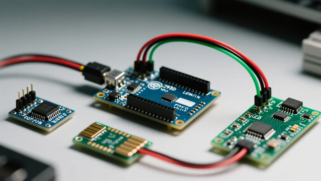
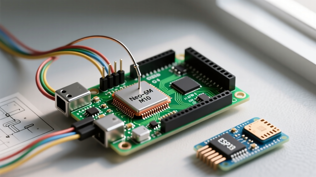
Integrating a GPS module for Arduino projects remains one of the most rewarding upgrades for makers building vehicle trackers, high-altitude balloons, or autonomous rovers. While the legendary u-blox NEO-6M dominated the maker space for over a decade, 2026 has seen a massive shift toward the u-blox M10 series. The M10 architecture offers concurrent reception of up to four GNSS constellations (GPS, GLONASS, Galileo, BeiDou) and drastically reduces power consumption to under 15 mA in tracking mode.
This comprehensive tutorial moves beyond generic wiring diagrams. We will cover exact hardware selection, logic-level safety, NMEA 0183 sentence parsing using the TinyGPSPlus library, and advanced troubleshooting for the most common edge cases that cause 'no fix' errors.
Hardware Selection: Choosing the Right Receiver
Before wiring, you must select the right receiver for your environment and budget. Clone boards flood the market, but understanding the underlying silicon is critical for reliable operation.
| Module / Silicon | Constellations | Avg. Price (2026) | Best Use Case | Interface |
|---|---|---|---|---|
| NEO-6M (Clone) | GPS Only | $5 - $8 | Basic logging, indoor education | UART (9600 baud) |
| NEO-M8N | GPS + GLONASS | $18 - $24 | Drones, standard vehicle tracking | UART, SPI, I2C |
| MAX-M10S | Quad-constellation | $25 - $35 | Battery-powered trackers, high-precision | UART, I2C (DDC) |
For new designs in 2026, we highly recommend the MAX-M10S based breakouts. The concurrent multi-constellation tracking drastically reduces the Time to First Fix (TTFF) in urban canyons where sky visibility is partially obstructed.
Step-by-Step Wiring Guide: UART & Logic Levels
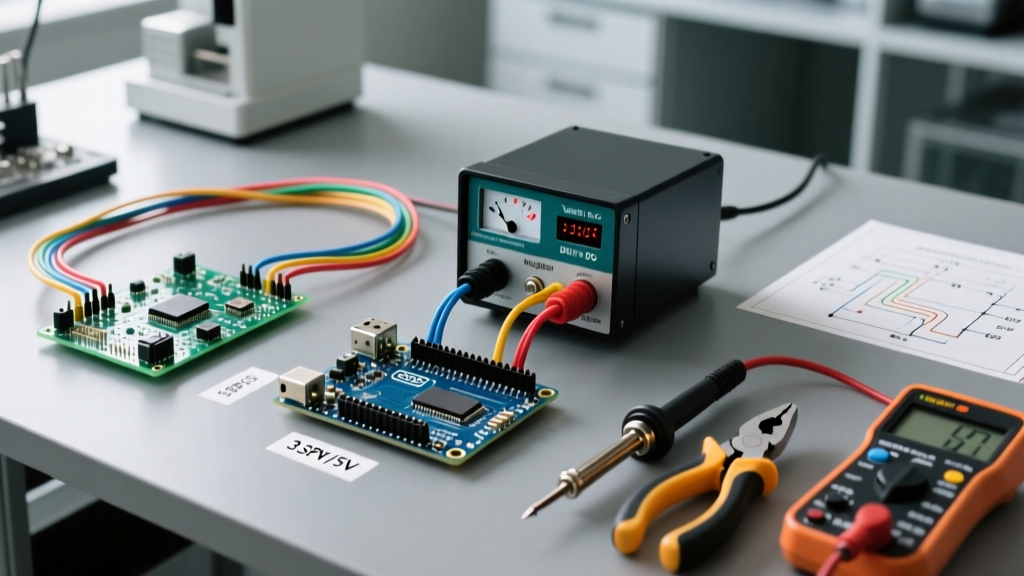
The most common hardware failure when connecting a GPS module for Arduino setups is ignoring logic level thresholds. Most u-blox chips operate natively at 3.3V. While many cheap Neo-6M breakout boards include an onboard LDO (Low Dropout Regulator) to accept 5V VCC, the RX data pin is often not 5V tolerant.
1. The Safe 5V Arduino Wiring (UNO R3 / Mega)
If you are using a 5V board like the classic UNO R3, you must step down the Arduino's TX pin to the GPS RX pin to prevent degrading the module's silicon over time.
- VCC: Connect to Arduino 5V (if breakout has LDO) or 3.3V (if raw module).
- GND: Connect to Arduino GND.
- GPS TX: Connect directly to Arduino Digital Pin 4 (SoftwareSerial RX).
- GPS RX: Connect through a voltage divider (e.g., 10kΩ and 20kΩ resistors) to Arduino Digital Pin 3 (SoftwareSerial TX).
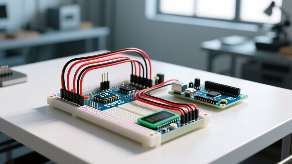
2. The Native 3.3V Wiring (Nano 33 IoT / ESP32)
When using 3.3V microcontrollers, wiring is direct. No level shifting is required.
- VCC: 3.3V
- GPS TX: ESP32 RX2 (GPIO 16)
- GPS RX: ESP32 TX2 (GPIO 17)
Coding the Arduino: Parsing NMEA Data
Raw GPS data outputs NMEA 0183 sentences—long strings of comma-separated ASCII text. Parsing these manually via string manipulation is a recipe for memory leaks and buffer overflows. Instead, we use the industry-standard TinyGPSPlus library by Mikal Hart.
Install the library via the Arduino IDE Library Manager, then upload the following optimized sketch. This example uses HardwareSerial on an ESP32 or Arduino Mega to prevent the timing jitter associated with SoftwareSerial at high baud rates.
#include <TinyGPSPlus.h>

TinyGPSPlus gps;

// Use HardwareSerial1 on ESP32 or Mega
#define GPS_RX 16
#define GPS_TX 17
#define GPS_BAUD 9600

void setup() {
  Serial.begin(115200);
  Serial1.begin(GPS_BAUD, SERIAL_8N1, GPS_RX, GPS_TX);
  Serial.println(F("GPS Module Initialized..."));
}

void loop() {
  // Feed data to the parser
  while (Serial1.available() > 0) {
    if (gps.encode(Serial1.read())) {
      displayInfo();
    }
  }

  // Timeout warning
  if (millis() > 5000 && gps.charsProcessed() < 10) {
    Serial.println(F("ERROR: No GPS data received. Check wiring!"));
    while(true);
  }
}

void displayInfo() {
  if (gps.location.isValid()) {
    Serial.print(F("Lat: ")); Serial.print(gps.location.lat(), 6);
    Serial.print(F(" Lon: ")); Serial.println(gps.location.lng(), 6);
    Serial.print(F("Satellites: ")); Serial.println(gps.satellites.value());
  } else {
    Serial.println(F("Searching for satellites..."));
  }
}
Deep Dive: Understanding NMEA Sentences & TTFF
To truly master your GPS module for Arduino, you must understand what the library is parsing. The two most critical sentences are GPRMC (Recommended Minimum) and GPGGA (Fix Data).
Expert Insight: If your module outputs 'GNGGA' instead of 'GPGGA', it means the receiver is using multiple GNSS constellations (e.g., GPS + Galileo) to calculate the fix. TinyGPSPlus handles this automatically in versions 1.0.3 and above.
The Cold Start Problem
Beginners frequently report that their GPS module 'is broken' because it outputs no location data for the first 5 to 15 minutes. This is known as a Cold Start. The module lacks the current almanac and ephemeris data required to calculate satellite trajectories. It must blindly search the sky across all possible frequencies and Doppler shifts. Once a lock is achieved, subsequent boots will experience a Hot Start (TTFF under 2 seconds), provided the module's backup battery (usually a rechargeable MS621FE or LIR2032) maintains the RTC and RAM.
Real-World Troubleshooting & Edge Cases
Even with perfect code, environmental and hardware edge cases will trip you up. Use this diagnostic matrix to solve 'no fix' issues.
- The 'Indoor Testing' Fallacy: GPS signals arrive at the Earth's surface at roughly -130 dBm, which is billions of times weaker than a standard Wi-Fi signal. They will not penetrate concrete, metal roofs, or energy-efficient Low-E glass. You must test your setup outdoors with a clear view of the sky. If testing indoors, you must use an active GPS antenna placed in a window, or utilize a GPS simulator for code testing.
- Baud Rate Mismatches: While 9600 baud is the NMEA standard, many modern M10 and M8 modules default to 115200 or 38400 out of the box. If your serial monitor shows garbled text or the TinyGPSPlus timeout triggers, use the u-blox U-Center software via a USB-to-Serial FTDI adapter to verify and reset the module's baud rate.
- Antenna Connection Loss: The u.FL / IPEX connectors on ceramic patch antennas are incredibly fragile. If you drop the module, the center pin can easily snap or lose contact. Always secure the antenna cable with a dab of hot glue or Kapton tape to prevent micro-disconnects during vibration.
- I2C (DDC) Address Conflicts: If you opt to use the I2C interface to save UART pins, the default u-blox address is
0x42. Ensure no other sensors on your I2C bus (like certain BME280 breakouts) are pulling the SDA line low, which will cause the GPS initialization to hang indefinitely.
Summary
Wiring a GPS module for Arduino requires more than just connecting four jumper wires. By selecting modern M10 silicon, respecting 3.3V logic thresholds, leveraging the TinyGPSPlus library, and understanding the physics of a cold start, you can build robust, commercial-grade tracking systems on a maker budget. For further reading on antenna placement and signal multipathing, consult the Adafruit Ultimate GPS Learning System.