
The Evolution of DIY Waveform Analysis
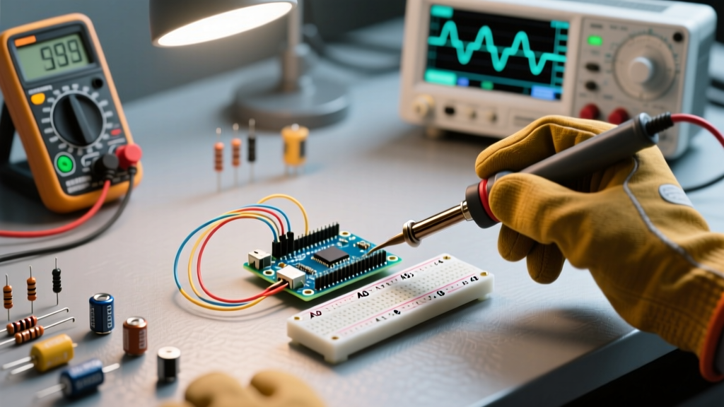
Building an Arduino oscilloscope remains a definitive rite of passage for embedded systems engineers, students, and hobbyists. In 2026, the landscape of DIY test equipment has matured significantly. We have moved past the days of simply polling analogRead() in a basic loop and hoping for the best. Today's community-driven projects leverage Direct Memory Access (DMA), 32-bit ARM Cortex-M architectures, and high-throughput binary serial protocols to achieve sampling rates that rival entry-level commercial digital storage oscilloscopes (DSOs).
In this community resource roundup, we break down the most effective hardware configurations, external ADC integrations, and software stacks for building a reliable Arduino oscilloscope. Whether you are debugging PWM motor controllers, analyzing audio signals, or capturing transient sensor spikes, this guide provides the actionable specifications you need.
Tier 1: The Audio-Range Basics (ATmega328P)
The classic Arduino Uno R3 (and its modern R4 counterparts) serves as the entry point for most DIY oscilloscope builds. The ATmega328P features a 10-bit Successive Approximation Register (SAR) ADC. According to the official Arduino analogRead() documentation, the default conversion time is roughly 100 microseconds, yielding a maximum theoretical sampling rate of about 9.6 kSPS (kilo-samples per second).
While sufficient for audio-range signals (up to ~4 kHz, respecting the Nyquist-Shannon sampling theorem), this falls short for capturing fast digital edges. Advanced community builds bypass the Arduino core library, directly manipulating the ADCSRA and ADCSRB registers to lower the ADC prescaler and enable free-running mode. This pushes the ATmega328P to its absolute hardware limit of ~15 kSPS, though at the cost of increased noise and reduced effective number of bits (ENOB).
Tier 2: 32-Bit DMA Powerhouses (SAM3X8E & STM32H7)
For makers requiring 1 MSPS (mega-sample per second) or higher, 8-bit AVRs are insufficient. The community has heavily standardized around 32-bit ARM boards for serious waveform analysis.
The Arduino Due (SAM3X8E)
Despite its age, the Arduino Due remains a staple in the DIY oscilloscope community. Its AT91SAM3X8E microcontroller boasts a 12-bit ADC capable of 1 MSPS. The critical advantage here is Direct Memory Access (DMA). By configuring the DMA controller to automatically transfer ADC conversion results into a RAM buffer, the CPU is completely freed from interrupt overhead. This ensures zero jitter between samples, a common failure mode in interrupt-driven AVR builds.
The Arduino Giga R1 WiFi (STM32H7)
For high-end 2026 builds, the Giga R1 WiFi utilizes the STM32H747XI dual-core processor. It features 16-bit ADCs capable of an astonishing 3.6 MSPS. Community developers utilize the STM32 Hardware Abstraction Layer (HAL) to chain timer-triggered ADC conversions with dual-buffer DMA, allowing for continuous, gapless waveform streaming over high-speed USB or Wi-Fi.
Bypassing the Bottleneck: External ADC Integration
When internal microcontroller ADCs lack the required bandwidth or resolution, the community turns to external SPI or parallel ADCs. A popular mid-tier choice is the MCP3208, a 12-bit, 8-channel SPI ADC. While its 100 kSPS limit isn't groundbreaking, its 12-bit resolution and low noise floor make it ideal for precision sensor logging, such as thermocouple or strain gauge monitoring.
For high-speed requirements, makers integrate CCD-grade parallel ADCs like the AD9226 (12-bit, 65 MSPS). Interfacing a parallel ADC requires a microcontroller with a Flexible Memory Controller (FMC) or external SRAM latching, pushing the project into advanced FPGA-adjacent territory.
The 2026 Community Software Stack
Hardware is only half the battle; visualizing the data stream without dropping frames is equally critical. While Java-based Processing was the default in the 2010s, the modern community has shifted toward more efficient tools.
- SerialPlot: An open-source, Qt-based application highly regarded for real-time binary stream decoding. As detailed in the SerialPlot GitHub repository, it supports custom binary framing, which eliminates the massive CPU overhead associated with parsing ASCII CSV strings over UART.
- Python + PyQtGraph: For advanced post-processing, FFT analysis, and automated triggering, makers write custom Python scripts utilizing PyQtGraph for GPU-accelerated rendering and PySerial for data ingestion.
- MegunoLite: A popular Arduino IDE serial plotter alternative that offers excellent CSV logging and UI customization for Windows users.
Hardware Comparison Matrix
Selecting the right microcontroller dictates your oscilloscope's bandwidth. Below is a comparison of the most popular community-approved boards for 2026 builds.
| Microcontroller Board | ADC Resolution | Max Practical Sample Rate | Approx. Cost (2026) | Best Use Case |
|---|---|---|---|---|
| Arduino Uno R3 (ATmega328P) | 10-bit | ~15 kSPS | $22.00 | Audio analysis, slow sensor logging |
| Arduino Due (SAM3X8E) | 12-bit | 1 MSPS (via DMA) | $45.00 | PWM debugging, ultrasonic sensors |
| Teensy 4.1 (i.MX RT1062) | 12-bit | ~1.2 MSPS | $32.00 | High-speed DSP, compact form factor |
| Arduino Giga R1 WiFi (STM32H7) | 16-bit | 3.6 MSPS | $135.00 | RF envelope tracking, precision lab use |
Critical Edge Cases: Input Protection & Aliasing
A common and catastrophic failure mode in DIY Arduino oscilloscope builds is destroying the microcontroller's ADC multiplexer via electrostatic discharge (ESD) or accidental connection to mains-referenced signals. Microcontroller pins are strictly limited to VCC (usually 3.3V or 5V) and GND.
Community Warning: Never connect raw, unconditioned signals directly to an Arduino analog pin. Ground loops between your PC's USB ground and the device under test (DUT) can introduce lethal voltage differentials to your MCU.
To protect your hardware, implement a three-stage analog front-end (AFE) protection network:
- Voltage Scaling: Use a high-impedance voltage divider (e.g., 100kΩ series, 10kΩ shunt) to scale a ±10V signal down to a safe 0-3.3V range.
- Current Limiting & Clamping: Place a 100Ω series resistor directly at the ADC pin to limit transient current. Clamp the node with dual Schottky diodes (like the BAT54S) to VCC and GND. Schottky diodes are mandatory due to their low forward voltage drop (~0.3V), which engages before the MCU's internal parasitic diodes.
- Charge Injection Filtering: Add a 100pF ceramic capacitor (C0G/NP0 dielectric) to ground. This forms a low-pass filter, mitigating high-frequency noise and reducing the ADC's internal sample-and-hold charge injection kickback.
Furthermore, beware of aliasing. If you are sampling a 10 kHz square wave at 15 kSPS, the Nyquist criterion is technically met, but the reconstructed waveform will look like a distorted sine wave. Community best practice dictates an oversampling ratio (OSR) of at least 10x to accurately capture digital rise and fall times.
Frequently Asked Questions
Can I use an Arduino oscilloscope to measure mains AC voltage?
No. Direct connection to mains AC is extremely dangerous and will destroy your board. To measure mains, you must use a galvanically isolated step-down transformer or a dedicated isolated current/voltage sensor module (like the ZMPT101B) with proper isolation ratings. Always verify isolation with a multimeter before connecting to your MCU.
Why does my waveform look noisy at high sample rates?
At high sampling rates, the ADC's internal sample-and-hold capacitor has less time to charge, leading to incomplete conversions and increased noise. Ensure your signal source has a low output impedance (under 10kΩ). If measuring high-impedance sources, add an external op-amp buffer (like the MCP6001) to drive the ADC pin.
How do I implement hardware triggering?
Software triggering (scanning the buffer for a threshold crossing) introduces jitter. For precise triggering, use the microcontroller's internal analog comparator to generate a hardware interrupt, or route the signal through an external fast comparator (like the LM393) to halt the DMA buffer capture exactly at the trigger edge. For more on Due hardware specs, refer to the Arduino Due hardware documentation.