
The Fundamental Answer: What Do Arduinos Do?
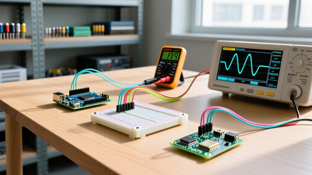
At the most basic level, if you are asking what do Arduinos do, the answer is that they act as the central nervous system for electronic projects. An Arduino reads physical inputs (like light levels from a photoresistor, temperature from a thermistor, or a button press), processes that data using a microcontroller, and triggers physical outputs (like spinning a DC motor, illuminating an LED matrix, or sending an MQTT payload via Wi-Fi).
However, for intermediate makers and engineers, the real question isn't just about the basic fetch-decode-execute cycle. The critical question is: How do Arduinos interface with the broader hardware ecosystem? Understanding what Arduinos do requires a deep dive into hardware compatibility, shield form factors, logic voltage thresholds, and power delivery limitations. In 2026, with the ecosystem split between legacy 8-bit AVR chips and modern 32-bit ARM Cortex architectures, navigating these compatibility layers is essential to prevent hardware damage and ensure reliable operation.
Hardware Compatibility: The Shield Ecosystem Matrix
Arduino shields are modular circuit boards that stack directly onto the microcontroller to add specific functionalities, such as motor control, GPS tracking, or cellular connectivity. But not all shields are universally compatible. Physical pin alignment and underlying bus architectures dictate what you can safely stack.
| Board Model | Microcontroller Architecture | Native Logic Voltage | Shield Form Factor | Max GPIO Current |
|---|---|---|---|---|
| Uno R4 WiFi | Renesas RA4M1 (32-bit ARM) | 5V Tolerant | Standard (R3) | 8 mA per pin |
| Mega 2560 | ATmega2560 (8-bit AVR) | 5V | Mega (R3 Extended) | 20 mA per pin |
| Nano 33 IoT | SAMD21 (32-bit ARM) | 3.3V | Nano (30-pin) | 7 mA per pin |
| Portenta H7 | STM32H747 (Dual-Core ARM) | 3.3V | Portenta (High-Density) | 16 mA per pin |
The SPI Pinout Trap
One of the most common compatibility failures occurs with SPI (Serial Peripheral Interface) shields. On a standard Uno R3, the hardware SPI pins are mapped to digital pins 11 (MOSI), 12 (MISO), and 13 (SCK). If you take an Ethernet shield designed for the Uno and plug it into an Arduino Mega 2560, the shield will physically fit, but it will fail to communicate. Why? Because on the Mega, the SPI bus is routed to pins 50, 51, and 52. The workaround is to utilize the 2x3 ICSP header, which maintains consistent SPI routing across almost all standard Arduino form factors.
The 5V vs. 3.3V Logic Level Compatibility Gap
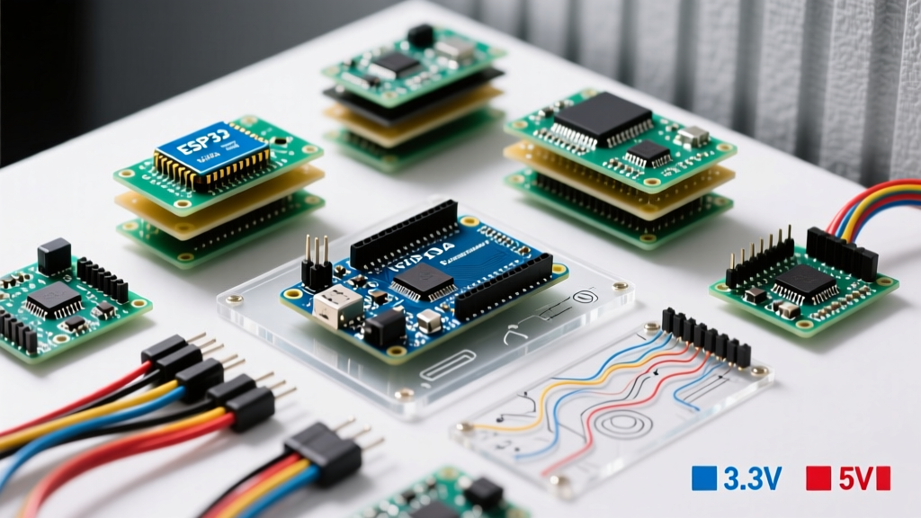
When evaluating what Arduinos do in sensor networks, you must address logic levels. Legacy boards like the Uno R3 operate at 5V logic. Modern sensors (like the BME280 or VL53L1X LiDAR module) strictly require 3.3V logic.
Connecting a 3.3V sensor directly to a 5V Arduino's I2C or SPI pins will push 5V into the sensor's data lines, instantly destroying the sensor's internal silicon. Conversely, connecting a 5V actuator to a 3.3V board like the Nano 33 IoT often results in the actuator failing to trigger, as 3.3V falls below the high-state threshold (Vih) of many 5V components.
Expert Compatibility Fix: Never rely on simple resistor voltage dividers for high-speed bidirectional data lines like I2C. The parasitic capacitance of the resistors will round off the square wave edges, causing data corruption at 400kHz. Instead, use a dedicated BSS138 MOSFET-based bidirectional logic level converter (typically costing around $2.95). For unidirectional signals (like triggering a 5V relay from a 3.3V ESP32), a simple NPN transistor like the 2N2222 is vastly superior and handles the current load safely.
For a comprehensive breakdown of voltage thresholds and translation methods, the SparkFun Logic Levels Tutorial remains the definitive engineering reference for maker hardware.
Power Delivery and Thermal Edge Cases
What Arduinos do is heavily constrained by their power delivery networks (PDN). A frequent mistake among beginners is powering high-draw components (like a 12V solenoid valve or a strip of 60 WS2812B NeoPixels) directly from the Arduino's 5V or Vin pins.
The LDO Thermal Shutdown Problem
Boards like the Uno R3 and Mega 2560 use an onboard Linear Dropout (LDO) regulator (typically the NCP1117) to step down voltage from the barrel jack or Vin pin to a stable 5V. Linear regulators dissipate excess voltage as heat.
Consider this real-world failure mode: You power your Arduino via the barrel jack with a 12V wall adapter and draw 150mA from the 5V pin to run a small servo. The power dissipated by the LDO is calculated as P = (Vin - Vout) × I.
P = (12V - 5V) × 0.15A = 1.05 Watts.
The SOT-223 package of the NCP1117 has a junction-to-ambient thermal resistance of roughly 104 °C/W. A 1.05W dissipation causes a temperature rise of over 109 °C above room temperature. The chip will rapidly hit its 150 °C thermal shutdown threshold, causing your Arduino to randomly reboot or permanently fail. Actionable advice: If your project draws more than 50mA from the 5V rail, bypass the onboard LDO entirely and use a dedicated buck converter (like the LM2596 module, ~$3.50) to step down 12V to 5V efficiently.
Software and IDE Compatibility
Beyond physical hardware, what Arduinos do is dictated by software compatibility. The transition to Arduino IDE 2.3.x and higher has unified the ecosystem, but managing board definitions remains a hurdle.
- AVR Boards (Uno, Mega, Nano): Natively supported via the legacy
avr-gcctoolchain. Compilation is fast, and memory mapping is straightforward. - ARM Cortex Boards (Portenta, Giga R1, Nano 33): Require specific CMSIS packs and board manager URLs. If you are integrating third-party boards like the ESP32-S3, you must add the Espressif Systems JSON URL to your
Additional Boards Manager URLsin the IDE preferences. - PlatformIO Integration: For complex projects utilizing RTOS (Real-Time Operating Systems) or dual-core architectures, professional developers bypass the Arduino IDE entirely in favor of PlatformIO within VS Code, which handles library dependency resolution and CMake build systems far more reliably.
You can verify official hardware specifications and software requirements directly via the Arduino Hardware Documentation Portal.
Real-World Troubleshooting: I2C Bus Collisions
When stacking multiple shields or wiring multiple sensors to the A4 (SDA) and A5 (SCL) pins, you are building a shared I2C bus. Every I2C module requires pull-up resistors (usually 4.7kΩ) on the data lines.
If you connect three different sensor modules, you are effectively placing three 4.7kΩ resistors in parallel, dropping the total pull-up resistance to roughly 1.5kΩ. This creates an overly strong pull-up, causing the microcontroller's open-drain outputs to struggle to pull the line low, resulting in corrupted data packets and Wire.endTransmission() errors. The fix: Use a multiplexer like the TCA9548A I2C hub (approx. $4.50) to isolate sensor buses, or physically scrape off the surface-mount pull-up resistors on secondary modules.
Frequently Asked Questions
Can I use a 5V shield on a 3.3V Arduino like the Nano 33 IoT?
Physically, yes, it will plug in. Electrically, it is risky. The Nano 33 IoT outputs 3.3V, which may not be recognized as a "HIGH" signal by 5V shields. Furthermore, if the shield sends 5V back to the Nano's RX/TX or I2C pins, it will fry the SAMD21 microcontroller. Always use a logic level shifter in between.
What do Arduinos do when they run out of SRAM?
Unlike a PC that uses virtual memory, an Arduino with exhausted SRAM (e.g., the 2KB limit on a classic Uno R3) will experience stack collisions. Variables will overwrite the call stack, leading to unpredictable behavior, frozen loops, or spontaneous reboots. To combat this, store static strings in flash memory using the F() macro, or upgrade to a board with more RAM, like the Mega 2560 (8KB) or the Portenta H7 (1MB).
Are third-party clone boards fully compatible with official shields?
Most UNO R3 clones (often priced around $12-$15) use the CH340 USB-to-Serial chip instead of the official ATmega16U2. While they are 100% compatible with standard shields, you must install the CH340 drivers on your host OS to upload code. Furthermore, some budget clones use thinner PCB traces for the power rails, meaning they should not be used for high-current applications like driving large stepper motors directly from the board's 5V bus.