
The Core Definition: What Are GPIO Pins?
At the most fundamental level of embedded electronics, you will inevitably encounter the term GPIO. But what are GPIO pins, and why do they dictate the success or failure of your microcontroller projects? GPIO stands for General Purpose Input/Output. These are the uncommitted, software-configurable digital signal pins on an integrated circuit (IC) or microcontroller unit (MCU). Unlike dedicated pins that are hardwired for specific functions like USB data lines or crystal oscillator inputs, GPIO pins are blank canvases. You, the maker, define their behavior via code.
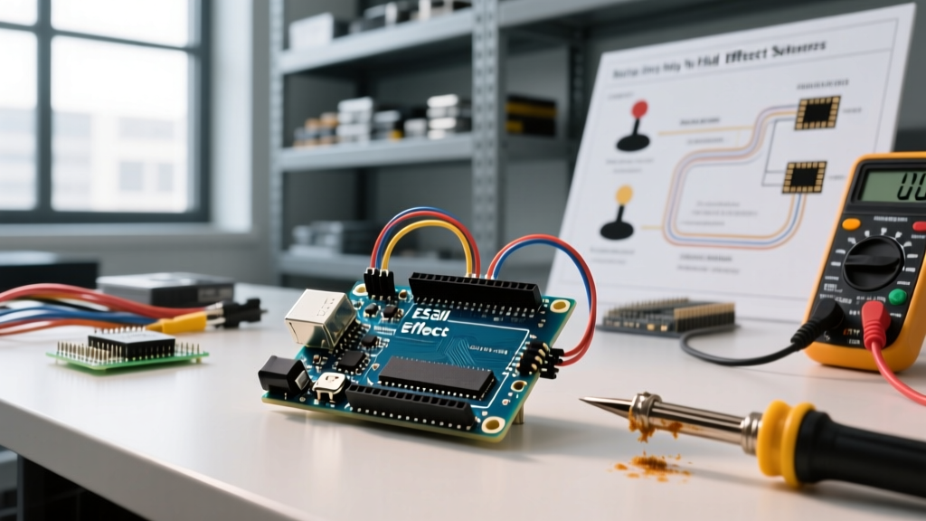
Whether you are blinking an LED on an Arduino Uno or reading a capacitive touch sensor on an ESP32, you are manipulating GPIO pins. Understanding their underlying architecture, electrical limits, and failure modes is what separates a novice who fries their board from an engineer who designs robust, production-ready hardware.
Inside the Silicon: How GPIO Registers Work
To truly grasp how these pins function, we must look past the Arduino IDE's digitalWrite() abstraction and examine the hardware registers. In classic 8-bit AVR architectures (like the ATmega328P found in the Arduino Uno), GPIO ports are grouped into letters (Port B, Port C, Port D). Each port is controlled by three distinct memory-mapped registers:
The Three Essential Registers
- DDRx (Data Direction Register): This register configures the pin as either an input or an output. Writing a '1' to a specific bit sets the corresponding pin as an output, while a '0' sets it as an input.
- PORTx (Data Register): When a pin is set as an output, the PORTx register determines whether the pin drives HIGH (VCC) or LOW (GND). When configured as an input, writing a '1' to the PORTx register activates the internal pull-up resistor.
- PINx (Input Pins Address): This register is used to read the actual physical logic level currently present on the pin, regardless of whether it is configured as an input or output.
When you call pinMode(pin, OUTPUT) in Arduino, the compiler translates this into a bitwise operation that flips the correct bit in the DDRx register. This direct register manipulation is why understanding Arduino's digital pin architecture is critical for optimizing execution speed in time-sensitive applications.
Electrical Characteristics and Absolute Maximum Ratings
A common pitfall when asking 'what are GPIO pins' is treating them as ideal voltage sources. They are not. Every GPIO pin is driven by internal MOSFETs that have strict resistance and current limitations. Exceeding these limits leads to thermal runaway, silicon degradation, or immediate catastrophic failure.
Sinking vs. Sourcing Current
Microcontrollers can either source current (current flows out of the pin to the load) or sink current (current flows from the load into the pin to GND). In many older architectures, the sink capability is slightly higher than the source capability due to the physical layout of the pull-down NMOS transistors versus the pull-up PMOS transistors.
For the ubiquitous ATmega328P, the official Microchip datasheet specifies an absolute maximum rating of 40mA per I/O pin. However, absolute maximums are stress ratings, not recommended operating conditions. Pushing a pin to 40mA will cause significant voltage droop and heat generation. The recommended continuous current is 20mA. Furthermore, the total current sourced or sunk across all ports combined must not exceed 200mA for the entire package.
Standard GPIO Operating Modes Explained
Modern microcontrollers offer a variety of GPIO configurations to interface with different external circuits safely.
- Push-Pull Output: The standard mode where the pin actively drives both HIGH and LOW states. Ideal for driving LEDs or logic inputs.
- Open-Drain (or Open-Collector): The pin can only pull the line LOW or leave it floating (high-impedance). This requires an external pull-up resistor and is mandatory for I2C communication buses, allowing multiple devices to share the same line without short-circuiting.
- Input with Internal Pull-Up: Connects the pin to VCC through a high-value resistor (typically 20kΩ to 50kΩ). This prevents the pin from 'floating' and picking up electromagnetic interference (EMI) when reading mechanical switches or pushbuttons.
Expert Insight: Never rely on internal pull-up resistors for high-impedance analog sensors or long wire runs. The internal resistance varies wildly with temperature and manufacturing tolerances. For precision applications, always use external 1% tolerance pull-up or pull-down resistors.
Comparative Analysis: GPIO Specs Across Popular MCUs
Not all GPIO pins are created equal. As you migrate from basic 8-bit boards to 32-bit powerhouses, the electrical rules change dramatically. Below is a comparison of GPIO characteristics across three staple maker platforms.
| MCU Platform | Logic Level | Max Continuous Current | Total Package Limit | Special Quirks |
|---|---|---|---|---|
| ATmega328P (Uno) | 5V | 20mA (40mA Abs Max) | 200mA | Robust, 5V tolerant, simple register mapping. |
| ESP32-S3 | 3.3V | 40mA (Source/Sink varies) | ~1100mA (Total I/O) | Strapping pins dictate boot mode; ADC2 conflicts with WiFi. |
| RP2040 (Pi Pico) | 3.3V | 4mA default (Configurable to 12mA) | 50mA (Total I/O ring) | Software-configurable drive strength and slew rate control. |
When working with 3.3V logic boards like the ESP32 or RP2040, connecting them directly to 5V peripherals will destroy the silicon. You must use logic level shifters or voltage dividers to bridge the gap safely. For a deep dive into ESP32 pinout limitations, refer to the Espressif technical documentation regarding strapping pins, which are sampled during the reset sequence to determine if the chip should enter flash mode or execute from SPI.
Real-World Failure Modes and Protection Strategies
Understanding what GPIO pins are theoretically is only half the battle. In the real world, wires act as antennas, and inductive loads fight back. Here are the most common ways makers destroy their MCU pins and how to prevent them.
1. Inductive Kickback
If you use a GPIO pin (via a transistor) to switch a relay, solenoid, or DC motor, turning the pin OFF causes the magnetic field in the coil to collapse. This generates a massive reverse voltage spike (often hundreds of volts) that will instantly punch through the GPIO's internal ESD protection diodes and fry the microcontroller. Solution: Always place a flyback diode (like a 1N4148 or 1N4007) in reverse bias across the inductive load.
2. The Backpowering Trap
Imagine a scenario where your microcontroller is powered off, but an external sensor connected to a GPIO pin remains powered by a separate 5V rail. The voltage from the sensor will travel through the GPIO pin, forward-biasing the MCU's internal ESD protection diodes, and effectively 'backpower' the chip through the I/O pin. This can cause erratic behavior, partial booting, or permanent latch-up. Solution: Use optocouplers for galvanic isolation between different power domains, or ensure all peripherals share a common ground and are switched off simultaneously via a master MOSFET.
3. Hot-Swapping Capacitive Loads
Connecting a long cable or a large capacitor to a GPIO pin while the system is live results in an inrush current that exceeds the pin's drive capability. Solution: Add a simple 220Ω to 330Ω series resistor on any GPIO pin that leaves the PCB. This limits the short-circuit current to safe levels without significantly affecting digital signal integrity at low frequencies.
Summary
So, what are GPIO pins? They are the vital sensory and motor pathways of any microcontroller, bridging the gap between digital logic and the physical world. By respecting their electrical boundaries, understanding their underlying register architecture, and implementing basic hardware protection, you ensure your embedded designs survive long past the prototyping phase.