
The Evolution of RepRap: Why RAMPS Still Matters in 2026
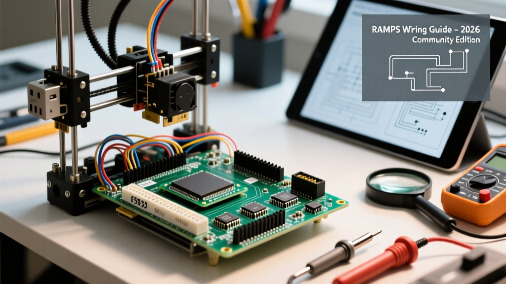
Learning how to use RAMPS Arduino setups effectively is a rite of passage for DIY 3D printing enthusiasts, CNC router builders, and laser engraver makers. While integrated 32-bit mainboards have largely dominated the commercial 3D printer market, the classic RAMPS 1.4 (RepRap Arduino Mega Pololu Shield) paired with an 8-bit Arduino Mega 2560 remains a vital staple in the open-source hardware community. Its modularity, ease of repair, and massive repository of community-driven modifications make it an unparalleled educational and prototyping platform.
In this 2026 community resource roundup, we move past the outdated, generic tutorials. We will dive deep into exact wiring schematics, modern silent stepper driver integrations (like the TMC2209), and the current Marlin firmware standards required to build a reliable, high-torque motion control system.
Community Hardware Breakdown: The 2026 Bill of Materials
Before soldering or plugging in a single wire, you must source the correct components. The community has largely standardized around specific upgrades to overcome the original 2014-era limitations of the RAMPS board. Below is the recommended 2026 Bill of Materials (BOM) for a robust 12V Cartesian setup.
| Component | Recommended Model | 2026 Avg. Price | Community Notes & Edge Cases |
|---|---|---|---|
| Microcontroller | Arduino Mega 2560 R3 | $18 - $28 | Avoid clones with CH340G USB chips if possible; ATmega16U2 is preferred for stable serial flashing. |
| Shield | RAMPS 1.4 | $12 - $16 | Ensure the PCB uses thick 2oz copper traces for the heated bed MOSFET to prevent thermal runaway. |
| Stepper Drivers | BigTreeTech TMC2209 V1.2 | $14 (pack of 5) | Replaces loud A4988s. Requires physical jumper removal for UART stealthChop mode. |
| Power Supply | Mean Well LRS-350-12 | $35 - $45 | 12V 30A is mandatory. Do not use 24V on standard RAMPS 1.4 without hardware modifications. |
| Heated Bed MOSFET | External IRLB3034PbF Module | $8 - $12 | Crucial upgrade. The onboard RAMPS MOSFET often melts under sustained 10A+ bed loads. |
Step-by-Step Wiring: Power and Logic Separation
The most common point of failure when figuring out how to use RAMPS Arduino boards is improper power distribution. The RAMPS shield splits power into two distinct circuits via two pairs of screw terminals. Miswiring these will instantly destroy your stepper drivers or the Arduino Mega itself.
- The 5A Circuit (Logic and Hotend): Connect your 12V positive and ground wires to the terminals labeled
5A. This circuit powers the Arduino Mega (via an onboard voltage regulator), the extruder heater cartridge, and the part-cooling fan. Warning: The Arduino's onboard regulator will overheat if input voltage exceeds 12V. - The 11A Circuit (Heated Bed): Connect the heavy-gauge (14 AWG minimum) wires from your power supply to the
11Aterminals. This circuit is dedicated solely to the heated bed. If you are using an external MOSFET module (highly recommended), you will wire the 11A terminals to the external module's input, and the RAMPSD8output to the module's signal pin. - Endstop Wiring: RAMPS endstop pins are configured as Signal, Ground, 5V (from left to right when looking at the board with power terminals at the bottom). Most mechanical endstops only require the Signal and Ground pins. Never wire 5V to a standard mechanical switch, as a misalignment can short the 5V rail and fry the Mega's ATmega2560 chip.
The TMC2209 UART Modification (Community Standard)
In 2026, running loud, legacy A4988 drivers is considered obsolete. The community standard is the TMC2209, which enables 'stealthChop' (silent operation) and 'Sensorless Homing' (stallGuard). However, RAMPS was not designed with UART pins for these drivers. Here is the community-verified workaround to enable UART communication:
- Remove the MS Jumpers: Pull all three microstepping jumpers (MS1, MS2, MS3) from the RAMPS headers beneath the driver.
- Bridge the Pins: On the TMC2209 driver itself, you must bridge the
MS1pad to theTXpad, and theMS2pad to theRXpad using a tiny solder jumper or jumper wire. - The 1k Resistor Rule: You must place a 1k ohm resistor on the TX line between the RAMPS header and the driver to prevent signal collision. Failing to do this will result in Marlin throwing 'TMC Connection Error' warnings on your LCD.
Flashing Marlin: Moving Beyond the Arduino IDE
If you are still using the legacy Arduino IDE to compile Marlin firmware, you are missing out on critical optimizations and modern safety features. The official Marlin project deprecated Arduino IDE support years ago. Today, the community strictly uses PlatformIO within Visual Studio Code.
'Compiling Marlin via PlatformIO ensures that the correct build flags, memory optimizations, and board definitions are applied automatically. It eliminates the 'sketch too large' errors that plague Arduino IDE users trying to enable advanced features like Linear Advance and Mesh Bed Leveling on 8-bit boards.' — Marlin Firmware Maintainer Documentation
To configure your Configuration.h for a RAMPS 1.4 setup, ensure the following flags are set:
#define MOTHERBOARD BOARD_RAMPS_14_EFB(For Extruder, Fan, Bed configuration)#define SERIAL_PORT 0#define BAUDRATE 250000(Standard for 8-bit Mega boards to ensure fast SD card reading)
For authoritative guidance on migrating your configuration files to the latest 2.1.x branch, always refer to the official Marlin Firmware documentation.
Top Community Resources and Repositories
The true power of the RAMPS ecosystem lies in its community. When you encounter edge cases or need custom 3D-printed mounts for your electronics enclosure, these are the definitive resources trusted by makers in 2026:
- The RepRap Wiki: The RAMPS 1.4 Hardware Page remains the holy grail for pinout diagrams, trace routing maps, and historical hardware revisions. It is essential for diagnosing short circuits.
- Printables & Thingiverse: Search for 'RAMPS 1.4 Enclosure with 40mm fan'. Proper cooling is non-negotiable; the stepper drivers will thermal-throttle at 65°C without active airflow.
- Arduino Official Docs: Understanding the underlying ATmega2560 architecture helps when debugging I2C LCD issues. The Arduino Mega 2560 documentation details the SDA/SCL pin locations on the AUX-1 header, which are required for modern REPRAP_DISCOUNT_FULL_GRAPHIC_SMART_CONTROLLER displays.
Troubleshooting Matrix: Real-World Failure Modes
Even with perfect wiring, 8-bit motion controllers present unique debugging challenges. Use this community-compiled matrix to diagnose the most frequent RAMPS failures.
| Symptom | Root Cause | Community-Verified Fix |
|---|---|---|
| Stepper motors vibrate but do not rotate | VREF voltage is too low, or coil wiring is mismatched. | Use a multimeter to adjust the driver potentiometer to 0.8V - 1.0V. Swap one coil pair (A and B) if timing is wrong. |
| Arduino Mega resets randomly during bed heating | Voltage drop on the 5A rail causing the Mega's brownout detector to trigger. | Upgrade to a higher gauge power wire on the 5A terminals and ensure the PSU is not sagging below 11.5V under load. |
| Heated Bed MOSFET melts or smokes | Sustained current exceeding 11A through the onboard PCB traces. | Immediately disconnect power. Bypass the onboard MOSFET and wire an external IRLB3034PbF module to the D8 output. |
| Marlin throws 'TMC Connection Error' | Missing 1k TX resistor or incorrect UART pin mapping in PlatformIO. | Verify the 1k resistor is soldered on the TX line. Ensure X_HARDWARE_SERIAL is defined correctly in Marlin's TMC config. |
| LCD shows garbled text or blank screen | I2C/SPI pin conflict or missing 5V on the AUX header. | Check the ribbon cable orientation. Ensure the Mega's 5V pin is properly seating into the RAMPS AUX-1 header. |
Final Thoughts on 8-Bit Motion Control
Mastering how to use RAMPS Arduino hardware is about more than just plugging in shields; it is about understanding power distribution, signal integrity, and firmware architecture. While 32-bit boards offer native silent drivers and faster processing, the RAMPS 1.4 and Mega 2560 combination teaches you the foundational electronics and debugging skills that apply to all CNC and robotics projects. By leveraging modern TMC drivers, external MOSFETs, and PlatformIO compilation, you can build a machine in 2026 that rivals commercial offerings in reliability and print quality.