
The Physics of Piezoelectricity in Microcontrollers
The term piezoelectricity originates from the Greek word piezein, meaning to squeeze or press. When subjected to mechanical stress, specific crystalline structures and ceramics generate an electrical charge proportional to the applied force. In the context of maker electronics, an arduino piezo setup typically relies on Lead Zirconate Titanate (PZT) ceramics bonded to a brass or stainless steel substrate. According to foundational materials science outlined in authoritative physics literature on piezoelectricity, this direct piezoelectric effect allows a simple 27mm brass disc to act as a highly sensitive solid-state accelerometer or knock sensor.
However, integrating these raw transducers with a 5V microcontroller like the ATmega328P requires more than just connecting two wires. The high-impedance nature of PZT elements and their tendency to generate massive voltage spikes under sharp impacts necessitate careful signal conditioning to prevent catastrophic silicon failure.
Direct vs. Converse Piezoelectric Effect
Before wiring your circuit, it is critical to distinguish between the two operational modes of piezo materials:
- Direct Effect (Sensor Mode): Mechanical deformation (bending, tapping, vibrating) generates a voltage differential across the ceramic faces. Used for knock detection, acoustic pickup, and vibration monitoring.
- Converse Effect (Actuator Mode): Applying an alternating voltage causes the ceramic to physically deform, generating sound waves. Used in piezo buzzers and ultrasonic transducers.
Component Identification: Raw Element vs. Active Buzzer
A frequent and frustrating edge case for beginners is purchasing the wrong component. If you buy a "5V Active Piezo Buzzer" from a generic electronics kit, it contains an internal oscillator circuit and will not work as an analog knock sensor. You must use a raw, passive piezo transducer element.
| Component Type | Internal Circuitry | Pinout | Use Case | Typical 2026 Cost |
|---|---|---|---|---|
| Raw PZT Element (e.g., Murata 7BB-27-4) | None (Passive) | 2 (Signal, Ground) | Analog knock/vibration sensor | $0.15 - $0.45 |
| Passive Piezo Buzzer | None (Resonant cavity) | 2 (AC Drive, Ground) | Tone generation via PWM | $0.50 - $0.90 |
| Active Piezo Buzzer | Internal Oscillator | 2 (DC VCC, Ground) | Digital alarm/notification | $0.80 - $1.50 |
The Hidden Danger: Voltage Spikes and ADC Frying
The most common failure mode in Arduino piezo projects is the destruction of the microcontroller's Analog-to-Digital Converter (ADC) multiplexer. When a 27mm piezo disc is struck firmly with a knuckle or hard object, the instantaneous open-circuit voltage can easily exceed 50V to 100V.
The ATmega328P datasheet specifies an absolute maximum voltage on any I/O pin of VCC + 0.5V (which equals 5.5V on a standard 5V Arduino Uno). Feeding a 50V spike directly into Analog Pin A0 will instantly punch through the internal ESD protection diodes, permanently shorting the ADC channel to the internal VCC rail.
Expert Warning: Never connect a raw piezo element directly to an Arduino analog pin without a high-value pull-down resistor and a voltage clamping mechanism. Relying solely on the microcontroller's internal protection diodes is a guaranteed path to hardware failure.
The Bulletproof Wiring Topology
To safely interface a high-impedance piezo sensor with a low-impedance microcontroller ADC, we must construct a signal conditioning circuit that bleeds excess charge and clamps transient spikes. Based on industrial sensor design principles and manufacturer application notes from Murata, the following topology is required.
Bill of Materials (BOM)
- 27mm Raw Piezo Element: Standard brass substrate with PZT ceramic.
- 1MΩ Resistor (1/4W): Acts as a pull-down to bleed the static charge generated by the high-impedance piezo source, allowing the voltage to return to 0V rapidly after an impact.
- 5.1V Zener Diode (1N4733A): Connected in reverse-bias parallel to the piezo. It remains non-conductive during normal taps but instantly shunts any voltage exceeding 5.1V to ground, protecting the Arduino.
- 100nF Ceramic Capacitor (Optional but recommended): Placed in parallel to form a low-pass RC filter, attenuating high-frequency electromagnetic interference (EMI) and dampening extreme mechanical ringing.
Step-by-Step Wiring Instructions
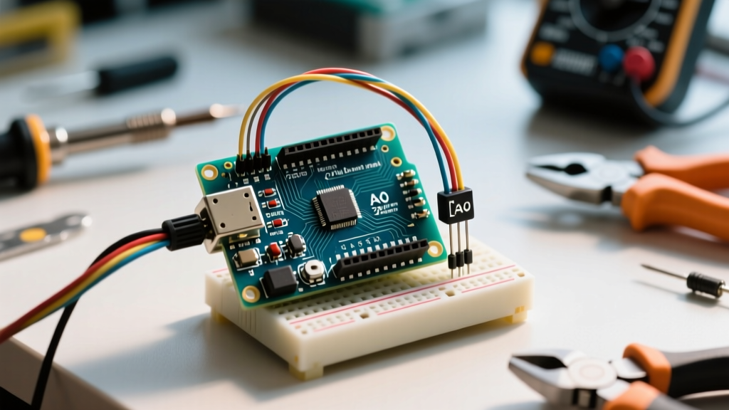
- Connect the Red wire (signal) of the piezo to Arduino Analog Pin A0.
- Connect the Black wire (ground) of the piezo to Arduino GND.
- Solder the 1MΩ Resistor in parallel across the Red and Black wires.
- Solder the 5.1V Zener Diode in parallel, ensuring the cathode (striped end) faces the Red wire and the anode faces the Black wire (GND).
Signal Conditioning and Code Implementation
With the hardware protected, the software must account for the mechanical realities of piezo ceramics. When struck, a piezo disc does not output a single clean voltage spike; it "rings" mechanically, producing a rapidly decaying sine wave of alternating positive and negative voltages (which the Zener and internal Arduino diodes clip to a 0V–5V square-ish wave).
This ringing means a single physical knock will trigger multiple `analogRead()` values above your threshold. Implementing a software dead-time (debounce) is mandatory. The standard Arduino Knock Sensor tutorial provides a baseline, but production-grade code requires dynamic thresholding.
Optimized C++ Logic Flow
Below is the conceptual logic for a robust knock detection routine:
- Baseline Sampling: Read the ambient noise floor on A0. In a quiet room, this should be 0-2. If it hovers around 15-20, you have severe EMI or a floating ground issue.
- Thresholding: Set a trigger threshold at least 4x above the noise floor (e.g., `threshold = 80`).
- Peak Detection: When `analogRead(A0) > threshold`, record the value. Do not trigger an event immediately.
- Debounce Delay: Wait 50ms to 100ms. This allows the mechanical ringing to dissipate. Any subsequent spikes during this window are ignored.
- Event Execution: After the dead-time, execute your payload (e.g., toggling an LED, sending an MQTT payload) and reset the state.
Common Failure Modes and Troubleshooting Matrix
Even with perfect wiring, environmental and mechanical factors can degrade sensor performance. Use this diagnostic matrix to resolve edge cases in your Arduino piezo deployment.
| Symptom | Root Cause | Engineering Solution |
|---|---|---|
| Sensor triggers randomly without physical contact. | High-impedance antenna effect picking up 50/60Hz mains hum or RF interference. | Add a 100nF ceramic capacitor in parallel with the 1MΩ resistor to create a low-pass filter. Ensure shielded cable is used if the piezo is >5cm from the MCU. |
| Sensor reads 1023 continuously after one hard knock. | ADC multiplexer latch-up or fried internal ESD diode due to overvoltage. | Verify Zener diode orientation. If the ATmega328P is already damaged, move to Analog Pin A1 and update code. Always use the Zener clamp. |
| Excellent response on a desk, but fails when mounted to a wall. | Acoustic impedance mismatch and mechanical damping by the mounting surface. | Mount the piezo using a thin layer of double-sided foam tape or hot glue around the outer brass edge only. Never glue the center ceramic dome, as this restricts flexion. |
| Sensitivity drops drastically in high-heat environments. | PZT ceramics approach their Curie temperature, losing piezoelectric domain alignment. | Standard PZT elements degrade above 80°C–120°C. For high-temp industrial applications, source Aluminum Nitride (AlN) based sensors instead. |
Advanced Applications: Beyond Simple Knocks
Once you master the signal conditioning required for an arduino piezo knock sensor, the same hardware topology unlocks advanced acoustic and structural monitoring capabilities. By sampling the ADC at high frequencies (using direct port manipulation to bypass the slow `analogRead()` overhead), you can perform Fast Fourier Transforms (FFT) on the piezo's output. This allows the microcontroller to distinguish between the acoustic signature of a knuckle tapping glass versus a metal tool striking a wooden desk, enabling sophisticated, multi-state security interfaces and industrial predictive maintenance monitors.