
The Hidden Cost of Poor Arduino Assembly
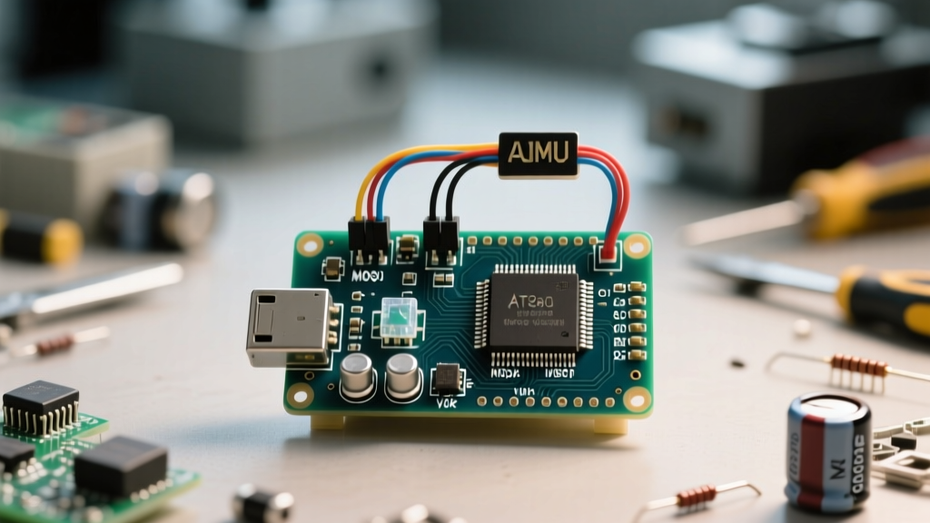
When an Arduino project fails to boot, resets randomly, or returns erratic sensor data, the immediate instinct is to blame the sketch. However, in professional electronics diagnostics, we know that up to 80% of 'unexplainable' microcontroller faults stem directly from physical Arduino assembly errors. Whether you are stacking shields on an Uno R3, wiring a custom PCB with an ATmega328P, or writing low-level AVR inline assembly code, the margin for error is razor-thin.
This guide bypasses basic 'check your USB cable' advice and dives deep into the electrical, thermal, and software-level assembly faults that plague maker projects in 2026. We will explore exact failure modes, diagnostic measurements, and systematic isolation protocols to get your build running flawlessly.
Top 4 Physical Arduino Assembly Errors
1. Shield Stacking and I2C Bus Collisions
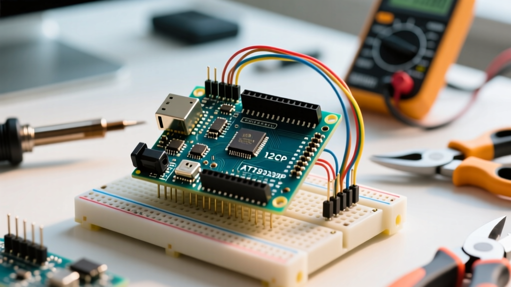
Stacking multiple shields is a hallmark of Arduino assembly, but it frequently leads to I2C (SDA/SCL) bus lockups. The ATmega328P I2C pins (A4 and A5 on the Uno) require pull-up resistors, typically 4.7kΩ to 5V. When you stack three shields that each include their own 4.7kΩ pull-ups, the resistors act in parallel. The effective pull-up resistance drops to roughly 1.56kΩ.
According to the Microchip ATmega328P Datasheet, the maximum sink current for an I/O pin is 20mA, but to maintain a valid logic LOW (below 0.6V at 5V VCC), you should not exceed 3mA to 5mA continuously. A 1.56kΩ pull-up forces the microcontroller to sink over 3.2mA just to pull the line low, leading to marginal logic levels, missed ACKNOWLEDGE bits, and complete bus freezes when high-speed sensors are polled.
Diagnosis: Use a logic analyzer to capture the SDA line. If the LOW state voltage hovers around 1.2V instead of dropping below 0.3V, you have a pull-up collision. Remove the surface-mount pull-up resistors on all but the master shield.
2. Breadboard Parasitic Capacitance and Contact Resistance
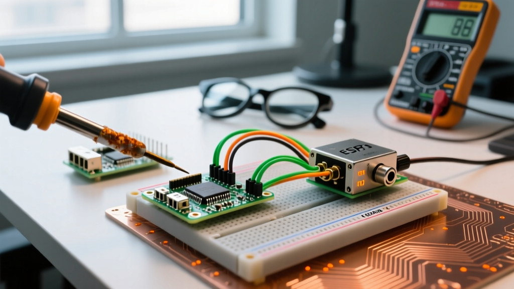
Breadboards are intended for prototyping, yet many permanent Arduino assemblies rely on them. Standard solderless breadboards exhibit 10pF to 50pF of stray capacitance between adjacent rows, and contact resistance that degrades from 0.1Ω to over 1.0Ω after 50 wire insertions.
When assembling high-impedance analog sensors (e.g., piezo vibration sensors or photoresistors exceeding 100kΩ), this parasitic capacitance forms an unintentional low-pass filter. More critically, the Arduino's internal ADC (Analog-to-Digital Converter) sample-and-hold capacitor requires a low-impedance source to charge fully within the 1.5 ADC clock cycles allocated for sampling. High breadboard contact resistance prevents this, resulting in wildly fluctuating analogRead() values.
3. Power Rail Thermal Throttling
A common Arduino assembly mistake is powering high-current peripherals (like 5V LED strips or servo motors) directly from the Uno's 5V pin while supplying 12V to the barrel jack. The onboard NCP1117-5.0 linear regulator must dissipate the voltage difference as heat.
The Thermal Math: If your circuit draws 400mA from the 5V rail and you supply 12V to the jack, the regulator dissipates Power = (12V - 5V) × 0.4A = 2.8 Watts. The SOT-223 package has a junction-to-ambient thermal resistance of ~50°C/W. This causes a 140°C temperature rise above ambient, instantly triggering the regulator's internal thermal shutdown at 150°C, causing the Arduino to brown-out and reset.
Diagnosis: Use a thermal camera or carefully touch the regulator. If it is too hot to hold your finger on for more than two seconds, bypass the onboard regulator and assemble a dedicated buck converter (like the LM2596) to feed the 5V pin directly.
4. Connector Crimping and JST Failures
Using Dupont or JST-XH connectors is standard in Arduino assembly, but improper crimping causes intermittent open circuits. A frequent error is using 24 AWG silicone wire in a terminal designed for 28 AWG wire. The crimp tabs fail to bite into the copper strands, relying solely on the insulation grip. Vibration from motors or relays breaks the connection.
Diagnostic Tool Matrix for Assembly Verification
To properly diagnose Arduino assembly faults, you need the right instrumentation. Below is a 2026 diagnostic matrix for hardware verification.
| Diagnostic Tool | Primary Assembly Fault Detected | Key Metric to Monitor | Approx. Cost (2026) |
|---|---|---|---|
| Logic Analyzer (e.g., Saleae Logic 8) | I2C/SPI bus collisions, timing violations | Protocol decoding, LOW state voltage thresholds | $120 - $150 |
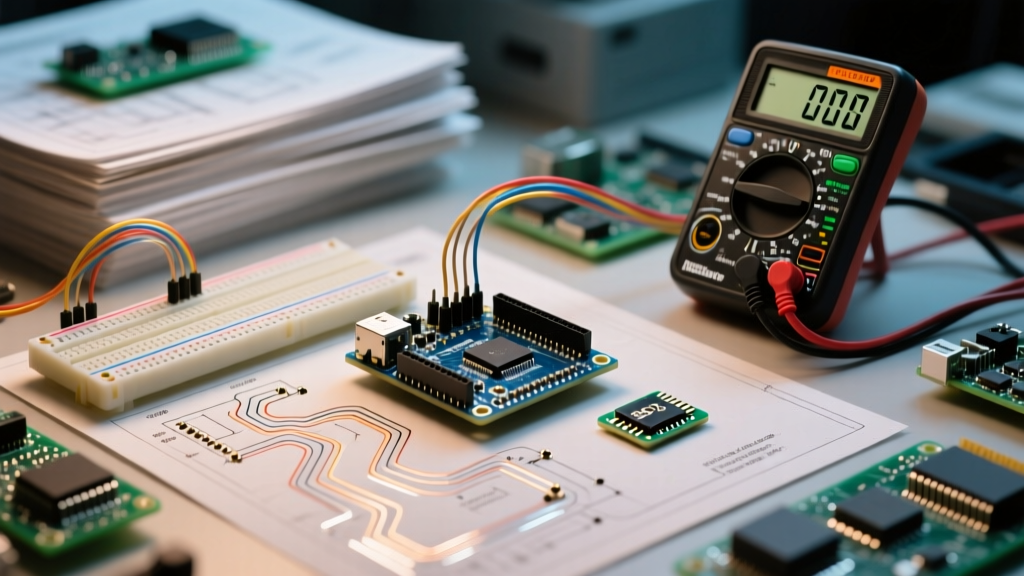
| Digital Multimeter (e.g., Fluke 117) | Power rail droop, short circuits, bad crimps | Voltage drop across traces, continuity resistance | $180 - $220 |
| Thermal Camera (e.g., FLIR ONE Edge Pro) | Regulator thermal throttling, shorted caps | PCB hotspots exceeding 85°C | $250 - $300 |
| Oscilloscope (e.g., Rigol DS1054Z) | Ground bounce, EMI from motors, parasitic ringing | Signal integrity, high-frequency noise on 5V rail | $350 - $400 |
Software Assembly: Diagnosing AVR Inline Assembly Errors
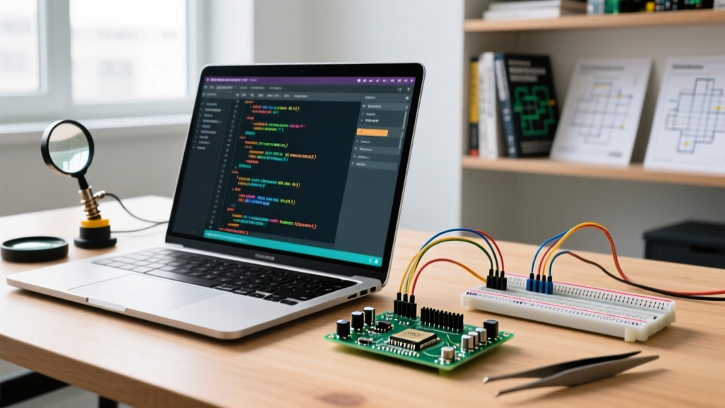
The term 'Arduino assembly' also applies to software—specifically, writing inline AVR assembly code within the Arduino IDE using the asm() or __asm__() directives to optimize timing-critical loops or interact with hardware registers directly.
Diagnosing inline assembly errors is notoriously difficult because the GCC compiler will not throw syntax errors for logical flaws in your register manipulation. The most common fatal error is an incomplete clobber list.
The Clobber List Trap
When you write inline assembly, you must tell the GCC optimizer which registers you are modifying. If you use Register 24 (r24) to perform a fast bit-shift but fail to list "r24" in the clobber list at the end of the asm volatile block, the compiler may have already stored a critical variable (like a loop counter or sensor state) in r24. Your assembly code silently overwrites it, causing the C++ code to behave erratically without throwing a single compilation warning.
Diagnosis: If your sketch compiles perfectly but produces random, non-deterministic logic errors only when compiler optimization (-Os or -O3) is enabled, inspect all asm() blocks. Ensure every modified register and the condition code register ("cc") are explicitly declared in the clobber list.
Step-by-Step Assembly Isolation Protocol
When faced with a non-functional build, follow this strict isolation protocol to identify the assembly fault without replacing components blindly.
- Visual and Olfactory Audit: Inspect under bright, angled light for cold solder joints (dull, grainy appearance) and flux residue bridges between ATmega328P TQFP-32 pins. Smell for ozone or burning rosin indicating a shorted ceramic capacitor.
- Power Rail Decoupling Check: With the MCU removed (if socketed) or the board unpowered, measure the resistance between the 5V and GND pins. A healthy Arduino assembly should read between 2kΩ and 10kΩ (due to reverse-polarity protection diodes and regulator internals). A reading below 50Ω indicates a solder bridge or a blown decoupling capacitor.
- Signal Integrity Verification: Connect an oscilloscope to the 5V rail. Trigger on the rising edge of a digital output pin switching a load (like a relay). Look for 'ground bounce'—a negative voltage spike on the ground reference that exceeds -0.5V. If present, your star-grounding assembly is flawed, and logic noise is coupling into the power plane.
- Peripheral Disconnect: Systematically unstack shields and disconnect I2C/SPI sensors one by one. If the system stabilizes upon removing a specific module, the fault is isolated to that module's bus capacitance or power draw.
Expert Tips for Bulletproof Builds
To prevent assembly errors before they occur, adopt these professional hardware integration standards:
- Use Star Grounding: Never daisy-chain high-current grounds (motors, relays) with logic grounds (sensors, MCU). Route them separately to a single common ground point to prevent voltage differentials that cause Texas Instruments documented ground loop noise.
- Upgrade Wire Gauge: For power rails carrying more than 500mA, abandon 28 AWG breadboard jumper wires. Use 22 AWG or 20 AWG silicone wire with properly crimped JST-XH connectors.
- Add Local Decoupling: Do not rely solely on the Arduino's onboard 100nF ceramic capacitors. When assembling long wire runs to remote sensors, solder an additional 100nF MLCC capacitor directly across the VCC and GND pins at the sensor end to suppress high-frequency EMI.
Mastering Arduino assembly requires shifting your mindset from purely writing code to understanding the physical realities of electrons, thermal dynamics, and signal integrity. By applying these diagnostic frameworks, you will eliminate the hidden hardware faults that cause 90% of maker project failures. For further hardware debugging, refer to the Arduino Official Hardware Support Documentation to cross-reference board-specific schematics.