
Arduino Shield: What Is It? The Core Concept
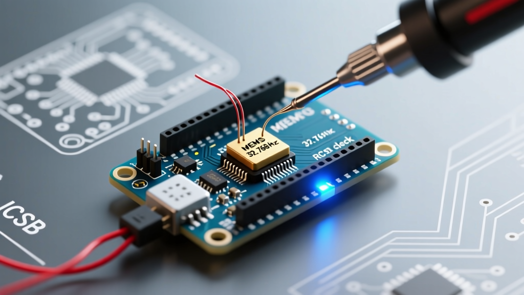
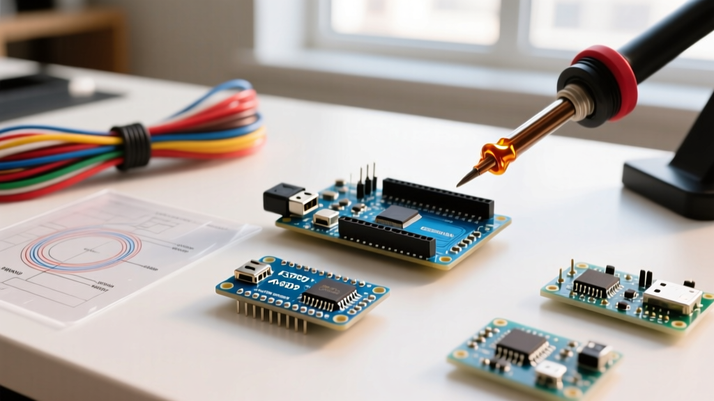
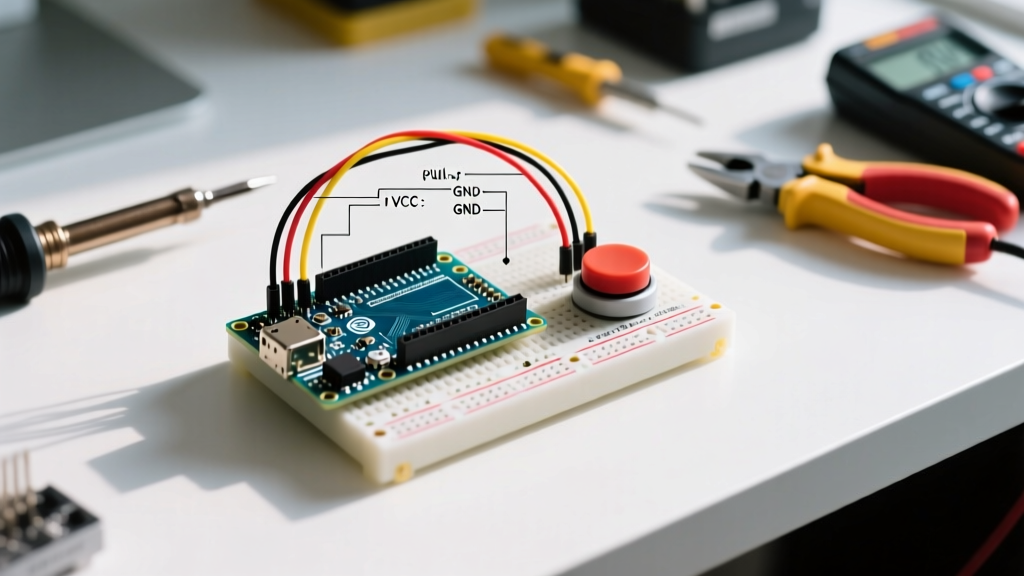
In the microcontroller ecosystem, an Arduino shield is a modular, stackable daughterboard designed to plug directly into the header pins of an Arduino development board (like the UNO or Mega). Instead of manually wiring sensors, motor drivers, or communication modules to a breadboard using jumper wires, a shield provides a pre-routed, plug-and-play hardware solution. This eliminates loose connections, reduces parasitic capacitance in high-speed buses, and dramatically accelerates prototyping.
Shields adhere to a standardized physical footprint—most commonly the R3 layout—ensuring mechanical and electrical compatibility across thousands of third-party and official add-ons. As of 2026, while system-in-package (SiP) boards and native IoT microcontrollers (like the ESP32 or Raspberry Pi Pico) handle many integrated tasks, shields remain the gold standard for industrial prototyping, heavy-load motor control, and legacy system integration.
The Physical Standard: R3 Footprint and Stacking Headers
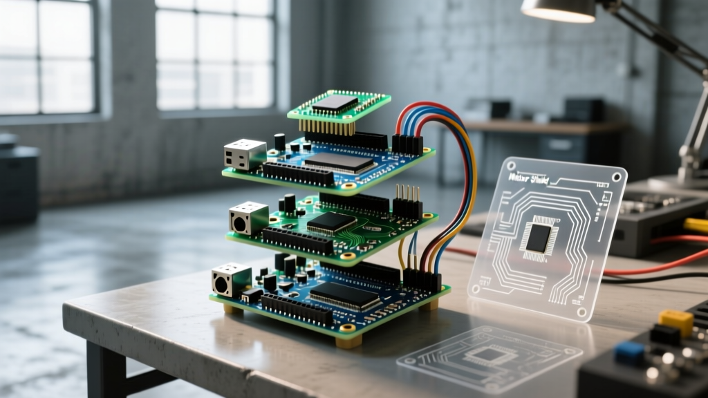
The standard Arduino UNO R3 footprint utilizes 0.1-inch (2.54mm) pitch female headers for the MCU side and pass-through male stacking headers on the top. This allows you to 'stack' multiple shields vertically. Key physical features include:
- Digital I/O Header: 14 pins (D0-D13, plus GND and AREF).
- Analog/Power Header: 6 analog pins (A0-A5) which double as secondary digital I/O or hardware interrupt pins on newer boards, alongside the power bus (VIN, GND, GND, 5V, 3.3V, IOREF).
- ICSP Header: A 2x3 pin header that bypasses the digital pins to provide direct access to the SPI bus (MISO, MOSI, SCK). This is critical because the SPI pins on the original UNO (D11-D13) were moved on the Arduino Mega 2560; the ICSP header ensures SPI shields remain compatible across both form factors.
Communication Protocols: How Shields Talk to the MCU
A shield is essentially a physical extension of the microcontroller's internal buses. Understanding which pins a shield consumes is vital to avoid 'pin collisions' when stacking multiple boards.
| Protocol | Standard UNO R3 Pins | Mega 2560 Pins | Common Shield Use Cases |
|---|---|---|---|
| I2C (TWI) | A4 (SDA), A5 (SCL) & Dedicated SDA/SCL headers | D20 (SDA), D21 (SCL) & Dedicated headers | OLED Displays, Motor Controllers (PCA9685), RTC modules |
| SPI | D10 (SS), D11 (MOSI), D12 (MISO), D13 (SCK) | D50 (MISO), D51 (MOSI), D52 (SCK), D53 (SS) | Ethernet (W5500), SD Cards, CAN Bus transceivers |
| UART (Serial) | D0 (RX), D1 (TX) | D0 (RX0), D1 (TX0) + 3 extra hardware UARTs | GPS Modules, RS-485 Industrial Adapters, Cellular modems |
2026 Shield Landscape: Essential Add-Ons and Real-World Pricing
The shield market has matured significantly. While basic sensor shields have been largely replaced by Qwiic/Stemma QT I2C ecosystems, high-power and specialized infrastructure shields remain highly relevant.
1. Motor Control Shields
Driving inductive loads like DC motors requires H-bridges and flyback diodes. Never drive motors directly from MCU GPIO pins.
- Arduino Motor Shield Rev3 (~$30.00): Based on the L298P dual full-bridge driver. It maps directly to digital pins but suffers from a ~2V voltage drop across the bipolar transistors, generating significant heat at currents above 1A. It also hardcodes several PWM pins, limiting servo usage.
- Adafruit Motor Shield V2 (~$24.95): A vastly superior design utilizing a PCA9685 I2C PWM controller and TB6612FET MOSFET drivers. Because it communicates entirely over I2C (default address 0x60), it frees up all digital PWM pins and drops only ~0.5V, running much cooler. It supports up to four DC motors or two steppers.
2. Ethernet and IoT Infrastructure Shields
For hardwired, low-latency industrial applications, Wi-Fi is often insufficient. The Arduino Ethernet Shield 2 (~$45.00) utilizes the W5500 TCP/IP offload chip. Unlike older ENC28J60 modules that require the MCU to process raw MAC frames (consuming massive RAM), the W5500 handles the TCP/IP stack in hardware, featuring a 32KB internal buffer. It connects via the hardware SPI bus and requires Pin 10 for the Chip Select (CS) line and Pin 4 for the onboard microSD card slot.
The UNO R4 Compatibility Challenge
With the widespread adoption of the Arduino UNO R4 Minima and WiFi (based on the 48MHz Renesas RA4M1 Cortex-M4), the definition of shield compatibility has shifted. While the R4 maintains the physical R3 footprint, there are critical electrical differences maker-engineers must account for:
⚠️ Hardware Warning: The A0 DAC Conflict
On the UNO R3, A0 is a standard analog input. On the UNO R4, A0 is routed to a 12-bit Digital-to-Analog Converter (DAC). Some poorly designed legacy shields hardwire A0 to GND or 5V for use as a digital control pin. Plugging these shields into an R4 and activating the DAC can short-circuit and permanently destroy the R4's DAC op-amp. Always check shield schematics before stacking on R4 boards.
Furthermore, while the R4 is 5V tolerant on its GPIO pins, its native logic threshold and SPI clock speeds (up to 24MHz) can cause timing failures on very old, bit-banged shields that rely on the slower 16MHz ATmega328P architecture.
Stacking Shields: Power Budgets and Bus Collisions
Stacking three or four shields is mechanically easy but electrically hazardous if you ignore power budgets and bus physics.
1. The 5V Rail Limit
The onboard linear regulator (or USB-C power path) on a standard UNO is typically limited to 1.0A to 1.5A. If you stack an LCD shield (drawing 200mA for the backlight) and a servo shield drawing 800mA for actuators, you will trigger the MCU's thermal shutdown or cause a brownout reset. Solution: Use shields that feature an independent VIN or EXT_PWR terminal block to supply high-current peripherals directly from an external buck converter, bypassing the MCU's fragile 5V rail.
2. I2C Pull-Up Resistor Collisions
The I2C bus requires pull-up resistors on the SDA and SCL lines (typically 4.7kΩ). If you stack three different I2C shields, and each has its own 4.7kΩ pull-ups physically soldered to the board, the equivalent parallel resistance drops to ~1.56kΩ. This creates a strong pull-up that requires the MCU's open-drain pins to sink more current to pull the line LOW. If the sink current exceeds the MCU's absolute maximum rating (often 3mA to 20mA depending on the chip), communication will fail, or the GPIO pin will degrade over time. Always inspect shield schematics and use a desoldering wick to remove redundant pull-ups on stacked boards.
Troubleshooting Common Shield Hardware Failures
When a shield fails to initialize, the issue is rarely the code. Use this diagnostic checklist for physical layer failures:
- Cold Solder Joints on Stacking Headers: Many budget shields ship with male headers that require user soldering. If the flux isn't properly activated, the ICSP or SPI pins may have high-resistance 'cold' joints. Reflow with a flux-core 63/37 Sn/Pb solder at 320°C for 2 seconds per pin.
- Logic Level Mismatch (3.3V vs 5V): If you are using a 3.3V MCU (like the Arduino Zero or Due) with a 5V shield, the SPI MISO line from the shield might not register as a logical HIGH on the 3.3V MCU. Use a bidirectional logic level shifter (like the BSS138 MOSFET circuit) between the shield and MCU.
- SPI Chip Select (CS) Conflicts: Every SPI device needs a unique CS pin. If an Ethernet shield uses D10 and an SD card shield also defaults to D10, the bus will deadlock. You must physically cut the CS trace on one shield and jumper it to an unused digital pin (e.g., D8), then update the corresponding
pinMode(8, OUTPUT)in your C++ sketch.
Summary
Understanding what an Arduino shield is goes beyond recognizing it as a simple plug-in accessory. It is a standardized hardware abstraction layer that manages power distribution, bus routing, and signal integrity. By carefully managing I2C addresses, respecting the SPI chip select lines, and calculating your 5V power budget, you can reliably stack complex systems—like a W5500 Ethernet logger driving an L298P motor array—without frying your microcontroller.