
Unlocking Capacitance Measurement on Microcontrollers
Measuring capacitance with an Arduino is a foundational skill that bridges basic physics and advanced sensor design. Whether you are building a non-contact liquid level sensor, designing capacitive touch buttons, or simply automating your workbench to sort through a bin of unmarked ceramic capacitors, understanding how to quantify capacitance is essential. While the Arduino Uno (ATmega328P) and newer boards like the Nano 33 IoT do not have native capacitance-to-digital converters (CDCs) built into their silicon, we can leverage their precise timing capabilities and digital I/O pins to measure capacitance accurately.
In this guide, we will explore the two primary methodologies for capacitance Arduino projects: the classic RC (Resistor-Capacitor) time-constant method for low-cost general-purpose measurement, and the use of dedicated CDC integrated circuits for high-resolution, noise-immune applications.
The Physics: RC Time Constants and the 0.693 Multiplier
To measure capacitance using basic digital pins, we rely on the charging curve of an RC circuit. When a capacitor charges through a resistor from a DC voltage source, the voltage across the capacitor follows an exponential curve. The standard time constant ($\tau$) is defined as $\tau = R \times C$, which represents the time it takes for the capacitor to charge to roughly 63.2% of the supply voltage.
However, a critical mistake many beginners make is using the 63.2% threshold in their Arduino code. Standard Arduino digital input pins do not trigger at 63.2% of VCC. According to the ATmega328P datasheet, the logic HIGH threshold ($V_{IH}$) is typically around $0.6 \times V_{CC}$, but the actual switching point for the pulseIn() function or a simple digital read often hovers right around 50% ($V_{CC}/2$).
The Mathematical Correction:
Using the capacitor charging equation $V(t) = V_{CC}(1 - e^{-t/RC})$, we set $V(t) = 0.5 V_{CC}$.
Solving for $t$ yields: $t = R \times C \times \ln(2)$.
Since $\ln(2) \approx 0.693$, the formula to find capacitance becomes:
$C = \frac{t}{0.693 \times R}$
Where $t$ is the time in microseconds, $R$ is the resistance in ohms, and $C$ is the capacitance in microfarads.
Method 1: The Basic RC Circuit (Low Cost, Broad Range)
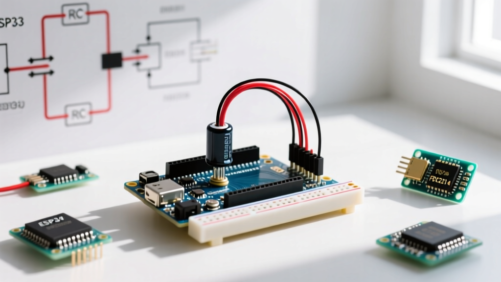
This method requires only a known resistor, the unknown capacitor, and three Arduino pins. It is highly effective for measuring electrolytic and film capacitors in the 1nF to 1000µF range.
Hardware Configuration
- Charge Pin (e.g., Pin 11): Configured as an OUTPUT. Drives HIGH to charge the capacitor through the resistor.
- Read Pin (e.g., Pin 13): Configured as an INPUT. Monitors the voltage across the capacitor.
- Discharge Pin (e.g., Pin 12): Configured as an OUTPUT. Drives LOW to discharge the capacitor before the next reading.
- Resistor: Placed between the Charge Pin and the Read Pin. Use a 10kΩ to 1MΩ 1% tolerance metal film resistor (e.g., Yageo MFR-25 series). Avoid 5% carbon film resistors, as their tolerance will directly corrupt your capacitance calculation.
Execution Logic
The Arduino sketch must first ensure the capacitor is fully discharged by setting the Discharge Pin LOW and the Charge Pin LOW for a few milliseconds. Next, the Charge Pin is set HIGH, and the micros() timer starts. The microcontroller polls the Read Pin until it registers a HIGH state, at which point the timer stops. You can read more about timing functions in the official Arduino micros() reference.
Method 2: Dedicated Capacitance-to-Digital Converters (High Precision)
When your project demands femtofarad (fF) resolution, high immunity to environmental noise, or the ability to measure extremely small changes in capacitance for touch-sensing or proximity detection, the RC method falls short. In 2026, the industry standard for advanced maker projects involves dedicated CDC ICs communicating via I2C or SPI.
The Texas Instruments FDC2214
The Texas Instruments FDC2214 is a 28-bit, 4-channel capacitance-to-digital converter. Unlike the DC-charging RC method, the FDC2214 uses an LC tank circuit. The capacitor under test is paired with an inductor to form an oscillator. The IC measures the resonant frequency of this tank circuit, which shifts based on the capacitance. This AC-based approach completely eliminates errors caused by dielectric absorption and provides immense noise rejection.
- Resolution: 28-bit (sub-femtofarad sensitivity).
- Cost: Breakout boards (like those from Adafruit or SparkFun) typically retail between $12.00 and $16.00.
- Best For: Non-contact liquid level sensing, high-precision soil moisture probes, and complex multi-zone capacitive touch interfaces.
Microchip CAP1203
If your goal is strictly capacitive touch buttons rather than raw component measurement, the Microchip CAP1203 is a specialized 3-channel touch sensor IC. It handles the baseline calibration, auto-recalibration, and threshold detection internally, outputting a simple I2C interrupt when a touch pad is activated. It costs roughly $1.50 per IC and saves hundreds of lines of DSP (Digital Signal Processing) code.
Method Comparison Matrix
| Feature | RC Time Constant (Arduino Pins) | FDC2214 (LC Tank CDC) | CAP1203 (Touch Controller) |
|---|---|---|---|
| Measurement Range | 1nF to 1000µF | 1pF to 100nF (High Precision) | 5pF to 50pF (Touch Pads) |
| Resolution | ~10-bit (Depends on timer) | 28-bit | Internal Threshold (8-bit ADC) |
| Hardware Cost | < $0.10 (Resistor) | ~$12.00 - $16.00 (Breakout) | ~$1.50 (Raw IC) |
| Code Complexity | Low (Basic timing) | Medium (I2C Register Config) | Low (I2C Interrupt polling) |
| Primary Use Case | Component sorting, basic level sensing | Precision proximity, fluid analysis | UI Buttons, wearables |
Real-World Failure Modes and Edge Cases
When deploying capacitance Arduino circuits in the field, theoretical math often collides with physical reality. Here are the most common failure modes and how to engineer around them:
1. Dielectric Absorption (Soakage)
If you measure an electrolytic capacitor using the RC method, discharge it, and immediately measure it again, the second reading will often be lower. This is due to dielectric absorption, where the internal dielectric material slowly releases trapped charge. Solution: Always implement a mandatory 500ms to 1000ms discharge-and-rest delay in your code between measurement cycles when testing electrolytics.
2. Temperature Coefficients in Ceramics
Not all capacitors are created equal. If you are using a ceramic capacitor as a reference or timing element in an RC circuit, check its dielectric code. X7R and Y5V ceramics exhibit massive capacitance shifts with temperature and applied DC bias voltage (sometimes losing up to 50% of their rated capacitance at VCC). Solution: Always use C0G/NP0 dielectric ceramics for precision timing and reference circuits, as they maintain a near-zero temperature coefficient.
3. VCC Ripple and ADC Noise
If you are powering your Arduino via a noisy USB port from a PC, the 5V rail will have high-frequency ripple. Because the RC threshold is tied to VCC, any ripple on the 5V rail directly modulates the trip-point of the digital input pin, causing jitter in your micros() readings. Solution: Power the RC network from the Arduino's 3.3V regulator pin, which is typically much cleaner, or use a dedicated low-dropout (LDO) regulator like the AMS1117-3.3 for the sensor circuit.
Summary
Mastering capacitance measurement on an Arduino opens the door to a vast array of sensor technologies. For quick workbench component verification or simple liquid-level switches, the RC time-constant method utilizing the 0.693 multiplier is cost-effective and educational. However, as maker projects evolve into commercial-grade products requiring environmental stability and sub-picofarad sensitivity, migrating to dedicated silicon like the FDC2214 is the definitive path forward. By understanding the parasitics of your breadboard, the dielectric properties of your components, and the timing thresholds of your microcontroller, you can engineer robust capacitive sensing systems for any application.