
The Reality of Switch Interfacing in Modern Microcontrollers
At first glance, wiring an Arduino with switch peripherals seems like the most basic task in embedded electronics: close the circuit, read a HIGH or LOW. However, as of 2026, with the proliferation of mixed-voltage development boards like the Arduino Nano ESP32 and the Uno R4 Minima, treating switches as simple ideal connections is a primary cause of erratic behavior, ghost triggers, and fried I/O pins. Switches are inherently messy analog components masquerading as digital inputs. They introduce contact bounce, floating nodes, electromagnetic interference (EMI), and voltage mismatches.
This compatibility guide breaks down the electrical realities of interfacing various switch types—mechanical, magnetic, and industrial—with modern Arduino architectures, providing exact component values, circuit topologies, and edge-case mitigations.
Logic Level & Voltage Compatibility Matrix
Before wiring any switch, you must verify the I/O logic level of your specific board. Applying a 5V pull-up to a 3.3V GPIO pin will degrade or destroy the microcontroller over time. Below is a compatibility matrix for popular boards when configuring internal pull-ups and reading switch states.
| Board Model (MCU) | Logic Level | Internal Pull-Up Range | Max Recommended Pin Sink Current | Switch Compatibility Notes |
|---|---|---|---|---|
| Uno R3 (ATmega328P) | 5.0V | 20kΩ - 50kΩ | 20mA (40mA absolute max) | Ideal for standard 5V mechanical switches. |
| Uno R4 Minima (RA4M1) | 5.0V | Configurable via registers | 20mA | Requires explicit INPUT_PULLUP; 5V tolerant. |
| Nano ESP32 (ESP32-S3) | 3.3V | ~45kΩ | 40mA (absolute max) | NEVER use 5V external pull-ups. Stick to 3.3V. |
| Due (SAM3X8E) | 3.3V | 50kΩ - 150kΩ | 15mA | Weak internal pull-ups; external 10kΩ recommended for noisy environments. |
The Floating Node & Pull-Up Configurations
A microcontroller I/O pin configured as an input has extremely high impedance (often >100MΩ). If a switch is wired between the pin and ground, but the pin is not pulled HIGH when the switch is open, the pin becomes a 'floating node.' It will act as an antenna, picking up ambient 50/60Hz mains hum and static electricity, resulting in random logic triggers.
Active-Low vs. Active-High Topologies
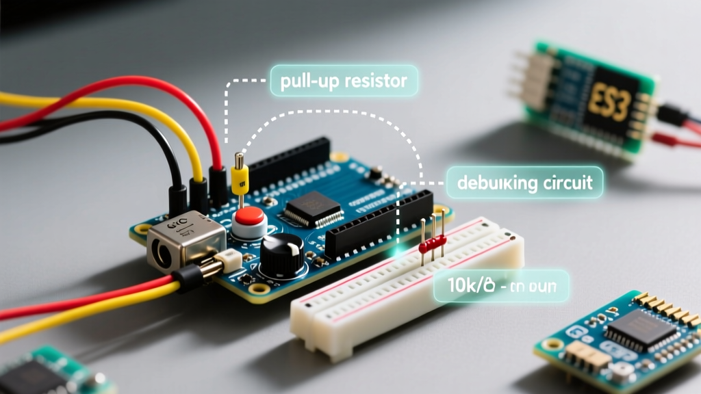
- Active-Low (Recommended): Wire the switch between the GPIO pin and Ground (GND). Enable the microcontroller's internal pull-up resistor using
pinMode(pin, INPUT_PULLUP);. When the switch is open, the pin reads HIGH. When closed, it shorts to GND and reads LOW. This eliminates the need for external resistors and leverages the native Arduino pinMode reference architecture. - Active-High: Wire the switch between the VCC (5V or 3.3V) and the GPIO pin. An external pull-down resistor (typically 10kΩ) must be wired between the pin and GND to prevent floating. This is generally discouraged unless interfacing with legacy systems that mandate active-high logic, as it requires extra components and draws continuous current when the switch is closed.
For a deeper understanding of why pull-up resistors are mandatory for preventing floating logic states, review the foundational SparkFun tutorial on pull-up resistors.
Electromechanical & Magnetic Switch Interfacing
Tactile, Toggle, and Limit Switches
Standard mechanical switches suffer from contact bounce. When the metal contacts close, they physically bounce apart and back together several times over a period of 1ms to 5ms before settling. To a microcontroller executing millions of instructions per second, this looks like the switch was pressed a dozen times in rapid succession.
Reed Switches & Contact Oxidation Edge Cases
Reed switches (glass-encapsulated magnetic contacts) are popular for DIY security and RPM sensing. However, they present a unique compatibility issue: contact oxidation. Because reed switches are often used in low-current, low-voltage 'dry' circuits, the contacts do not generate enough heat to burn off microscopic oxidation layers. This can result in a closed switch exhibiting 50Ω to 200Ω of resistance.
The Fix: The internal 30kΩ pull-up of an ATmega328P is usually sufficient to read through this resistance, but on 3.3V boards with weaker pull-ups, the voltage drop might not pull the pin below the logic LOW threshold (typically 0.3 * VCC). Always use an external 4.7kΩ pull-up resistor for reed switches on 3.3V architectures to ensure a hard LOW state.
Industrial 24V Switches: Optoisolation Requirements
Makers frequently attempt to interface industrial CNC limit switches or PLC inductive proximity sensors (which operate at 24V DC) directly with an Arduino. This will instantly destroy the microcontroller. You must use galvanic isolation.
⚠️ CRITICAL WARNING: 24V Industrial Switch Interfacing
Never wire a 24V switch directly to a 5V or 3.3V Arduino pin, even with a voltage divider. Industrial environments suffer from massive inductive kickback and ground loops. Always use an optocoupler like the PC817 (approx. $0.15 per unit).
PC817 Optocoupler Wiring Topology
- Input Side (24V Domain): Wire the 24V switch in series with a 2.2kΩ (1/4W) current-limiting resistor to the Anode (Pin 1) of the PC817. Connect the Cathode (Pin 2) to the 24V system Ground.
- Output Side (Arduino Domain): Connect the Emitter (Pin 3) to the Arduino GND. Connect the Collector (Pin 4) to the Arduino GPIO pin.
- Logic: Enable
INPUT_PULLUPon the Arduino pin. When the 24V switch closes, the internal LED illuminates, triggering the phototransistor to pull the Arduino pin LOW. The two circuits share no common ground, completely eliminating ground loop noise.
Debouncing: Hardware vs. Software Approaches
As detailed in comprehensive All About Circuits guides on switch bouncing, you must filter out the mechanical noise. You have two primary paths:
1. Software Debouncing (The Maker Standard)
Avoid using delay() to debounce, as it halts the entire microcontroller. Instead, use the Bounce2 library. It tracks the state of the pin and only registers a change if the pin remains stable for a defined interval.
#include <Bounce2.h>
Bounce debouncer = Bounce();
void setup() {
  pinMode(2, INPUT_PULLUP);
  debouncer.attach(2);
  debouncer.interval(5); // 5ms debounce window
}
2. Hardware Debouncing (For Interrupts & Noisy Environments)
If your switch is connected to a hardware interrupt pin, software debouncing can still result in missed or double-counted interrupts. Use an RC low-pass filter combined with a Schmitt trigger.
- RC Filter: Place a 10kΩ resistor in series with the switch, and a 100nF ceramic capacitor from the GPIO pin to GND. This creates a time constant ($\tau = R \times C$) of 1ms, smoothing out the bounce.
- Schmitt Trigger: Because the RC filter creates a slow voltage ramp (which can cause the MCU to linger in the undefined 'linear' region between HIGH and LOW), pass the signal through a 74HC14 Hex Inverter. The Schmitt trigger hysteresis will snap the slow ramp into a perfect, instantaneous digital square wave.
Long Wire Runs, ESD, & Signal Integrity
When routing an Arduino with switch inputs located more than 2 meters away (e.g., a garage door reed switch or an outdoor weather station tip-bucket), the wire acts as an antenna. A nearby lightning strike or even a person shuffling across a carpet can induce enough Electrostatic Discharge (ESD) to latch up or fry the MCU's I/O port.
Protective Measures for Long Runs
- Twisted Pair: Always use Cat5e or Cat6 cable. Route the switch signal and the GND reference on a twisted pair to cancel out common-mode magnetic interference.
- Series Termination: Solder a 100Ω to 330Ω resistor directly at the Arduino GPIO pin. This limits the instantaneous current spike from an ESD event before it reaches the delicate silicon junction inside the MCU.
- TVS Diode: Place a 5V (or 3.3V) bidirectional Transient Voltage Suppression (TVS) diode (like the 1N4148WS for low capacitance, or a dedicated 5.0V TVS) between the GPIO pin and GND to clamp voltage spikes safely to ground.
Summary
Successfully pairing an Arduino with switch hardware requires moving beyond simple continuity checks. By respecting the logic-level voltage limits of modern 3.3V boards, leveraging INPUT_PULLUP to prevent floating nodes, isolating high-voltage industrial sensors with optocouplers, and implementing robust hardware or software debouncing, you ensure your embedded projects operate reliably in the real world.