
Beyond the Basic NeoPixel: Why Migrate Your Addressable LEDs?
For the past decade, the WS2812B (commonly known as the NeoPixel) has been the undisputed king of maker lighting. However, as projects in 2026 demand higher frame rates for persistence-of-vision (POV) displays, better color rendering for photography, and seamless integration with 3.3V microcontrollers like the ESP32-S3 and Raspberry Pi Pico RP2040, the standard WS2812B is showing its age. If you are hitting flicker issues on camera, struggling with muddy white colors, or dealing with WiFi-interrupt timing glitches, it is time to upgrade your RGB LED on Arduino and compatible microcontroller ecosystems.
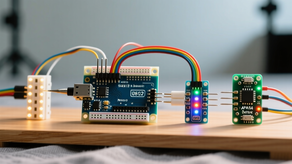
This migration guide will walk you through transitioning from standard 3-channel WS2812B strips to the 4-channel SK6812 RGBW for superior color accuracy, or the SPI-driven APA102 (DotStar) for ultra-high refresh rates. We will cover the exact hardware modifications, power injection math, and library code changes required for a flawless upgrade.
The Baseline: WS2812B Limitations in Modern Projects
Before ripping out your existing wiring, it is crucial to understand the specific failure modes of the WS2812B that necessitate an upgrade:
- Timing Sensitivity: The WS2812B relies on an 800kHz single-wire protocol where the duration of the high/low voltage states dictates the data. On MCUs with heavy background interrupts (like ESP32 WiFi stacks), this strict timing can be disrupted, causing random LED flickering or color shifts.
- PWM Frequency: The internal PWM frequency of the WS2812B is roughly 400Hz. While fine for the human eye, this low frequency causes severe banding and flicker when recorded on smartphone cameras or DSLRs operating at standard shutter speeds.
- Color Mixing: Generating pure white requires turning on the Red, Green, and Blue diodes simultaneously. This draws maximum current (approx. 60mA per LED) and often results in a cool, slightly bluish white due to diode efficiency variances.
Migration Path 1: SK6812 RGBW for Color Accuracy
The SK6812 RGBW is a direct footprint-compatible upgrade to the WS2812B, but it adds a dedicated white phosphor diode. Available in Warm White (3000K), Neutral White (4000K), and Cool White (6000K) variants, the SK6812-RGBW-V2 series solves the muddy color problem.
Hardware and Power Adjustments
Because you are adding a fourth diode, the power envelope changes dramatically. A standard 5-meter strip of 60 LEDs/m WS2812B draws roughly 18W (3.6A at 5V). The equivalent SK6812 RGBW strip draws up to 24W (4.8A at 5V) when all four channels are maxed out.
Pro-Tip: When upgrading to RGBW, do not reuse your old 10A power supply if you plan to run more than 3 meters of 60 LED/m strip. Upgrade to a dedicated 5V 15A (75W) enclosed switching power supply, such as the Mean Well LRS-75-5, to prevent brownout resets on your Arduino or ESP32.
Software Migration: The FastLED RGBW Hurdle
Migrating your code to the SK6812 requires careful library selection. The FastLED library is the industry standard for complex animations, but it does not natively support 4-byte RGBW data packets. If you push 3-byte CRGB data to an RGBW strip, the data stream will desync, and every fourth LED will display garbage data.
Your two migration options:
- Switch to Adafruit NeoPixel: This library natively supports RGBW. Initialize your strip using
Adafruit_NeoPixel(LED_COUNT, DATA_PIN, NEO_GRBW + NEO_KHZ800). You can then use thestrip.setPixelColor(i, r, g, b, w)method. - Use a FastLED Fork: If you must use FastLED's advanced math functions, you need to implement a custom
CRGBWstruct or use community-maintained forks like FastLED_RGBW, which map the 4-byte protocol correctly over the single data line.
Migration Path 2: APA102 DotStar for Speed and Stability
If your project involves POV fans, high-speed camera recording, or heavy MCU multitasking, the APA102 (often branded as Adafruit DotStar) is the ultimate upgrade. Unlike the single-wire WS2812B, the APA102 uses a standard SPI protocol requiring both a Data (MOSI) and Clock (SCK) line.
Why the Clock Line Changes Everything
Because the APA102 reads data on the clock edge rather than relying on microsecond pulse widths, it is completely immune to MCU interrupt latency. You can pause the data stream mid-frame, handle a WiFi packet or a sensor read, and resume without corrupting the LED state. Furthermore, the APA102 boasts a PWM frequency of over 20kHz, rendering it completely flicker-free on high-speed cameras.
Comparison Matrix: Choosing Your Upgrade
| Feature | WS2812B (Baseline) | SK6812 RGBW (Color Upgrade) | APA102 DotStar (Speed Upgrade) |
|---|---|---|---|
| Protocol | 1-Wire (800kHz) | 1-Wire (800kHz) | SPI (Data + Clock) |
| Channels | 3 (RGB) | 4 (RGBW) | 3 (RGB) + Global Brightness |
| PWM Frequency | ~400 Hz | ~400 Hz | >20,000 Hz |
| Interrupt Safe? | No | No | Yes |
| Avg Cost (5m, 60LED/m) | $15 - $18 | $22 - $26 | $35 - $45 |
| Best Application | Basic ambient lighting | Under-cabinet / architectural | POV displays / Video recording |
Critical Wiring Upgrades: Level Shifting and Power Injection
Regardless of whether you choose SK6812 or APA102, modern 3.3V microcontrollers require strict attention to signal integrity. The Adafruit NeoPixel Überguide has long warned about marginal logic levels, and this becomes a hard failure point when upgrading to longer, higher-speed strips.
The 3.3V to 5V Logic Level Problem
Both WS2812B and SK6812 datasheets specify a high-level input voltage (Vih) of 0.7 × VDD. If VDD is 5V, the data line must see at least 3.5V to register a logic HIGH. An ESP32 or RP2040 outputting 3.3V is operating in the undefined marginal zone. This often manifests as the first LED in the chain flickering or acting as a random number generator.
The Fix: Integrate a dedicated logic level shifter. The 74AHCT125 or SN74LVC1T45 chips are ideal. Power the chip's VCC with 5V, feed your MCU's 3.3V data pin into the input, and route the output to the LED strip's DIN. This guarantees a crisp 5V logic signal.
Power Injection Math for 2026 High-Density Strips
If you are upgrading to 144 LEDs/m strips, voltage drop across the strip's internal PCB traces will cause the far end to turn brown or pink (as the blue and green diodes require higher forward voltages than red).
- Rule of Thumb: Inject 5V and GND at both ends of a 5-meter strip for 60 LEDs/m.
- High Density: For 144 LEDs/m (drawing up to 8.6A per meter), you must inject power every 1 meter using 18 AWG silicone wire.
- Capacitor Sizing: Always place a 1000µF, 6.3V (or higher) electrolytic capacitor at the primary power injection point to absorb inrush current spikes when the strip transitions from black to full white.
Summary of Migration Steps
Upgrading your RGB LED on Arduino or ESP32 platforms is not a simple drop-in replacement; it requires recalculating your power budget and adapting your software architecture. If your priority is architectural lighting and realistic whites, migrate to the SK6812 RGBW and switch to the Adafruit NeoPixel library. If your priority is high-speed camera work, POV props, or interrupt-heavy IoT environments, route the extra clock line and migrate to the APA102 DotStar using FastLED's native SPI hardware acceleration. By addressing logic level shifting and strict power injection, your upgraded lighting rig will deliver professional, flicker-free performance.