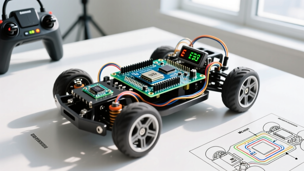

When building a remote control car with Arduino, most makers begin with the classic starter kit formula: an Arduino Uno, an L298N motor driver, and a basic Bluetooth module. While this setup is perfect for learning the fundamentals of PWM and serial communication, it quickly becomes a bottleneck when you demand higher speeds, longer range, and real-time telemetry. As the maker component landscape has evolved through 2026, upgrading your rig is more accessible and affordable than ever.
This migration guide will walk you through transforming a sluggish, toy-grade prototype into a high-performance, low-latency RC vehicle. We will cover microcontroller migration, modern motor drivers, radio link upgrades, power delivery overhauls, and non-blocking software architectures.
Phase 1: Microcontroller and Motor Driver Migration
The most critical flaw in the classic Arduino Uno and L298N combination is the voltage drop. The L298N uses Bipolar Junction Transistors (BJTs), which inherently drop about 2V to 3V across the H-bridge. If you supply 7.4V from a battery pack, your motors only see ~5V, resulting in massive efficiency losses and excessive heat generation.
To fix this, we migrate to modern MOSFET-based drivers and 32-bit microcontrollers. Below is a comparison of the legacy setup versus modern upgrade paths.
| Component Tier | MCU | Motor Driver | Voltage Drop | Peak Current | PWM Frequency | Est. Cost (2026) |
|---|---|---|---|---|---|---|
| Legacy (Starter) | Arduino Uno (ATmega328P) | L298N (BJT) | ~2.0V - 3.0V | 2A per channel | ~490 Hz | $18 |
| Intermediate | ESP32-S3 (Dual-Core) | TB6612FNG (MOSFET) | < 0.5V | 3.2A per channel | Up to 100 kHz | $14 |
| Advanced (Pro) | Teensy 4.1 (600MHz) | DRV8701 (Smart Gate) | Negligible (External FETs) | 12A+ (Configurable) | Hardware PWM up to 150 kHz | $45 |
The TB6612FNG Sweet Spot
For 90% of DIY RC car upgrades, the Pololu TB6612FNG dual motor driver is the ultimate migration target. It handles 1.2A continuous current per channel (with a 3.2A peak) and operates at a much higher PWM frequency. This eliminates the audible, high-pitched whine associated with the 490 Hz default PWM of the Arduino Uno, resulting in a silent, smooth throttle response.
Phase 2: Upgrading the Radio Link
If your current remote control car with Arduino relies on an HC-05 Bluetooth Classic module or an IR receiver, you are dealing with severe latency and range limitations. Bluetooth Classic introduces a 30ms to 50ms delay due to packet buffering and serial baud-rate bottlenecks, making high-speed cornering nearly impossible.
Migrating to 2.4GHz Transceivers
- NRF24L01+ PA+LNA: By adding a Power Amplifier (PA) and Low Noise Amplifier (LNA) to the standard NRF24L01+, you can achieve ranges exceeding 800 meters in open line-of-sight. More importantly, the SPI-based communication drops control latency to under 2 milliseconds.
- ESP-NOW (If using ESP32): If you migrate your car's brain to an ESP32, you can utilize the ESP-NOW protocol. This connectionless Wi-Fi protocol bypasses the standard TCP/IP stack, allowing for peer-to-peer packet transmission with latencies averaging 1.5ms to 3ms, without requiring a Wi-Fi router.
Pro-Tip: When mounting a 2.4GHz antenna on a carbon fiber or metal chassis, ensure the antenna element is positioned vertically and at least 2 inches away from the main battery and motor wires to prevent signal desensitization.
Phase 3: Power Delivery and Brownout Prevention
A common failure mode when upgrading to faster motors is the 'brownout reset.' High-torque brushed DC motors can draw 5A to 10A during a stall or hard acceleration. If your MCU shares the same voltage regulator as the motors, this massive current spike causes the logic voltage to sag below 3.3V, instantly resetting your Arduino mid-drive.
The LiPo and UBEC Migration
- Ditch the AA Batteries: Migrate from 4x AA NiMH cells (which suffer from high internal resistance and voltage sag) to a 2S LiPo battery (7.4V, 1500mAh, 50C discharge rating). The 50C rating ensures the battery can safely deliver 75A continuously without damaging the cells.
- Isolate the Logic Rail: Do not use the onboard 5V regulator of the Arduino or the 5V output of the motor driver. Instead, install a dedicated UBEC (Universal Battery Eliminator Circuit). A Hobbywing 5V/6A UBEC costs around $12 and uses a high-efficiency switching regulator to provide a rock-solid 5V rail to your microcontroller, completely isolated from motor-induced voltage sags.
Phase 4: Software Architecture (Migrating to FreeRTOS)
The standard Arduino `loop()` with `delay()` functions is fundamentally incompatible with high-performance RC vehicles. Blocking code prevents the MCU from reading encoder ticks or processing radio failsafes in real-time.
By migrating to an ESP32 or Teensy, you unlock the ability to use FreeRTOS, a real-time operating system that allows you to pin specific tasks to specific CPU cores.
Dual-Core Task Allocation Strategy
| Core | Assigned Task | Priority | Tick Rate |
|---|---|---|---|
| Core 0 | Radio RX, Telemetry TX, Failsafe Monitoring | High (Priority 3) | 100 Hz |
| Core 1 | Motor PID Control, Encoder Interrupts, Steering Servo | Critical (Priority 5) | 1000 Hz (1ms loop) |
This separation ensures that even if the radio packet takes an extra millisecond to parse on Core 0, Core 1 continues to execute the PID loop for the traction motors, keeping the car stable and preventing spin-outs.
Edge Cases: EMI and Ground Loops
Brushed DC motors are essentially noisy generators. The carbon brushes arcing against the commutator generate massive Electromagnetic Interference (EMI), which can corrupt I2C sensor data (like IMUs for traction control) and trigger phantom interrupts on encoder pins.
The EMI Mitigation Checklist
- Decoupling Capacitors: Solder 0.1µF ceramic capacitors directly across the positive and negative terminals of each brushed motor.
- Ferrite Beads: Thread your motor encoder wires through ferrite beads near the MCU to choke high-frequency RF noise.
- Star Grounding: Never daisy-chain your grounds. Route the high-current motor ground, the battery ground, and the logic ground to a single, centralized copper bus bar or heavy-gauge star point to prevent ground loop voltage offsets.
- Optocouplers: If you are reading wheel speed sensors near the motor axles, pass the signal through a high-speed optocoupler (like the 6N137) to physically break the electrical connection between the noisy motor domain and the sensitive logic domain.
Conclusion
Migrating your remote control car with Arduino from a beginner prototype to an advanced RC platform requires a holistic approach. By swapping the inefficient L298N for a MOSFET driver, upgrading to a 2.4GHz low-latency radio link, isolating your power delivery with a UBEC, and implementing a FreeRTOS dual-core architecture, you will achieve a level of responsiveness and reliability that rivals commercial off-road RC rigs. The hardware investments outlined in this guide total less than $60 in 2026, making it one of the most cost-effective performance upgrades you can undertake in the robotics space. For further reading on smart gate drivers for larger scale RC builds, consult the Texas Instruments DRV8701 datasheet and application notes.