
The Piezo Trap: Why Starter Kit Buzzers Fail in Production
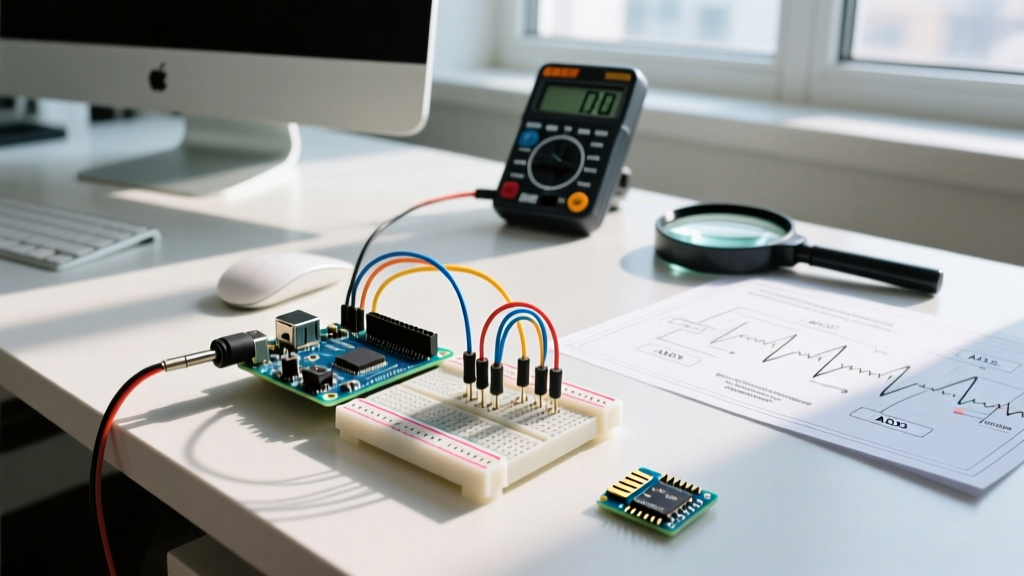
Every maker’s journey begins with the same ubiquitous component: the 5V active piezo buzzer. Whether you are building a simple alarm clock or a proximity sensor, the standard arduino and buzzer combination is the default for audio feedback. However, as projects graduate from breadboard prototypes to commercial production in 2026, the limitations of basic piezo transducers become glaringly obvious. They produce harsh, single-frequency square waves, lack dynamic range, and can actually degrade your microcontroller's GPIO pins over time.
Piezo buzzers are fundamentally capacitive loads. When driven directly by a 16MHz ATmega328P (the chip on the classic Arduino Uno), the rapid charging and discharging of the piezo element can cause transient current spikes. While a standard CPT-9019S piezo buzzer costs roughly $0.15 in bulk and draws an average of 30mA, those transient spikes can brush against the ATmega328P’s absolute maximum rating of 40mA per pin. Over thousands of actuation cycles, this electromigration weakens the silicon, leading to premature MCU failure in field-deployed devices.
To build robust, professional-grade products, engineers must migrate away from direct-GPIO piezo driving and embrace hardware-level audio protocols. This guide details the complete migration path from basic PWM buzzers to high-fidelity I2S MEMS audio systems.
Audio Feedback Evolution: Component Comparison Matrix
Before rewriting your firmware, it is critical to understand the hardware landscape. The table below compares the three primary stages of MCU audio feedback, reflecting 2026 market availability and pricing.
| Technology | Example Component | Avg. Cost (2026) | Audio Quality | MCU Overhead | Best Use Case |
|---|---|---|---|---|---|
| Direct Piezo | CPT-9019S (Active) | $0.15 | Poor (Harsh Square Wave) | Low (Blocking tone()) |
Disposable toys, basic alarms |
| PWM Amplified | PAM8403 + 40mm Speaker | $1.85 | Fair (Filtered PWM) | Medium (Timer Interrupts) | Consumer appliances, retro gaming |
| I2S Class-D / MEMS | MAX98357A + 3W Speaker | $6.50 | Excellent (16/24-bit PCM) | Low (Hardware DMA) | Medical devices, IoT voice, premium UX |
The MCU Bottleneck: Why You Must Upgrade the Brain
You cannot achieve high-quality audio on an 8-bit AVR microcontroller using software emulation. The standard Arduino tone() function relies on hardware timers to generate a 50% duty cycle square wave. It is strictly monophonic and blocks or interferes with other timer-dependent libraries (like Servo or PWM motor control).
Furthermore, generating true Pulse Code Modulation (PCM) audio—required for playing .WAV files, voice prompts, or polyphonic chimes—requires a Digital-to-Analog Converter (DAC) or an advanced high-resolution PWM setup. The 8-bit resolution of standard AVR PWM results in a quantization noise floor that is unacceptable for modern consumer electronics.
The 2026 Migration Standard: ESP32-S3 and RP2040
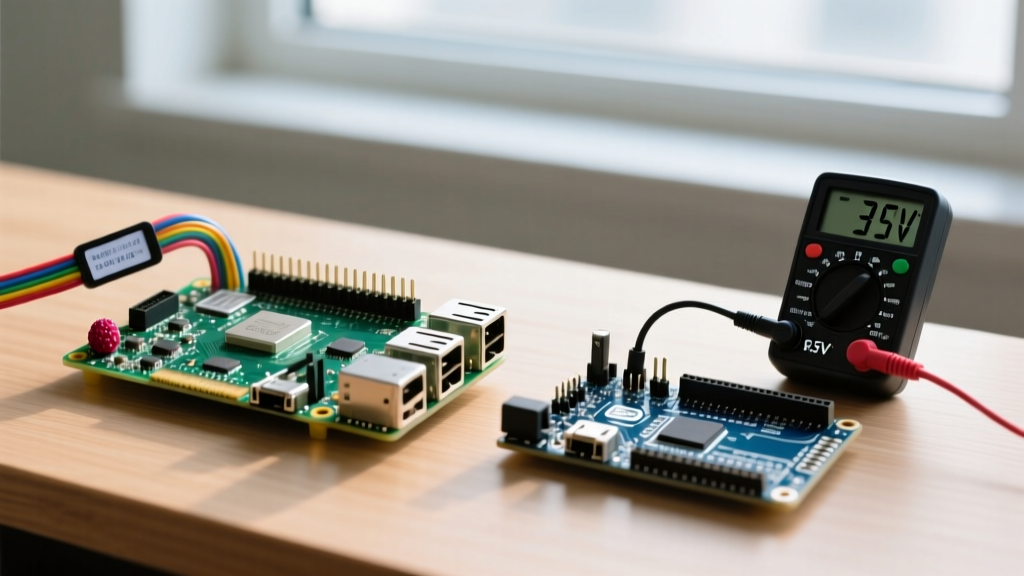
To unlock professional audio, your migration must include a microcontroller upgrade. The current industry standards for maker-to-pro transitions are the Espressif ESP32-S3 and the Raspberry Pi RP2040. Both chips feature dedicated I2S (Inter-IC Sound) hardware peripherals and Direct Memory Access (DMA) controllers. This allows the MCU to stream 16-bit or 32-bit audio data directly from Flash or RAM to an external DAC without burdening the CPU cores.
Hardware Migration: Integrating the MAX98357A I2S Amplifier
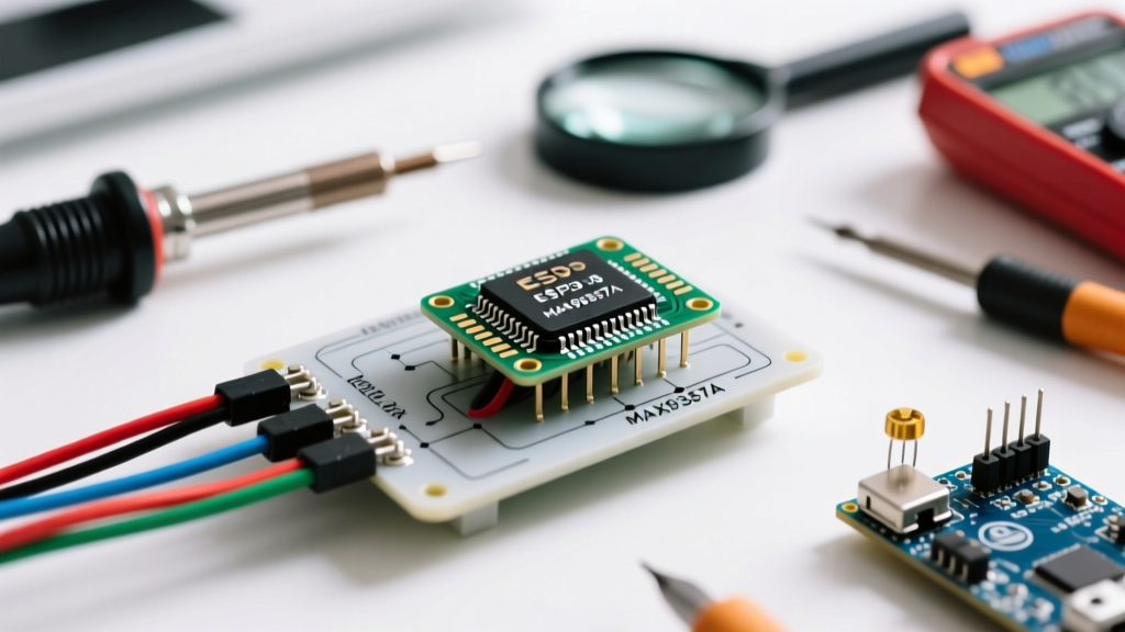
The most reliable bridge between a digital MCU and an analog speaker is the MAX98357A. This chip combines an I2S receiver with a high-efficiency Class-D amplifier. According to the Adafruit MAX98357A technical guide, it delivers up to 3.2W of power into a 4-ohm speaker while maintaining a remarkably low total harmonic distortion (THD+N) of 0.04%.
Wiring the I2S Bus
Unlike analog connections, I2S requires precise synchronization via three shared digital lines, plus power and ground. When migrating your PCB or breadboard, map the following pins:
- BCLK (Bit Clock): Synchronizes individual bits. Runs at Sample Rate × Bit Depth × Channels (e.g., 44.1kHz × 16 × 1 = 705.6kHz).
- LRC (Left/Right Clock / Word Select): Operates at the exact sample rate (e.g., 44.1kHz). Dictates when a new audio sample begins.
- DIN (Serial Data): The actual PCM audio payload.
- GAIN (Gain Select): Tie to GND for 12dB, leave floating for 15dB, or tie to VCC for 18dB.
- SD (Shutdown): Active low. Connect to a GPIO pin to physically mute the amp and eliminate idle hiss, or tie to GND for always-on.
Engineering Note: Never route I2S traces over split ground planes. The high-frequency BCLK signal (often exceeding 1MHz for high-res audio) will generate electromagnetic interference (EMI) and cause severe jitter if the return path is compromised. Use a solid, continuous ground pour on your PCB's Layer 2.
Software Migration: From tone() to I2S DMA
Migrating your codebase requires abandoning the blocking tone(pin, frequency, duration) paradigm. Instead, you will utilize the Arduino I2S.h library (natively supported in the Raspberry Pi Pico Arduino core and the ESP32 Arduino core).
Below is the architectural shift required to play a 16-bit, 44.1kHz mono audio sample stored in Flash memory.
Step 1: Define the I2S Configuration
Instead of setting a pin HIGH or LOW, you configure the hardware DMA buffers. A typical buffer size of 512 to 1024 samples prevents audio stuttering during heavy CPU tasks like Wi-Fi polling or sensor reading.
#include <I2S.h>

const int sampleRate = 44100;
const int bitsPerSample = 16;

void setup() {
  I2S.setAllPins(8, 9, 10); // BCLK, LRC, DIN for RP2040
  if (!I2S.begin(I2S_PHILIPS_MODE, sampleRate, bitsPerSample)) {
    Serial.println('Failed to initialize I2S!');
    while (1); // Halt execution on hardware failure
  }
}
Step 2: Streaming via DMA
In your main loop or a dedicated FreeRTOS task (on the ESP32), you feed the I2S buffer. Because I2S is stereo by hardware definition, mono audio must be duplicated to both the Left and Right channels to prevent the audio from playing at half-speed or dropping octaves.
void playAudioSample(int16_t sample) {
  // Duplicate mono sample to L and R channels
  I2S.write(sample);
  I2S.write(sample);
}
For complex projects involving Wi-Fi audio streaming or voice synthesis, Espressif provides a highly optimized ESP-IDF I2S API that includes built-in resampling and automatic channel formatting, which is highly recommended for production ESP32-S3 firmware.
Production Edge Cases and Troubleshooting
Migrating to I2S solves the audio quality problem, but introduces new RF and digital failure modes that do not exist with simple piezo buzzers. Prepare for the following edge cases during your validation phase:
1. The 'Pop and Click' Boot Sequence
The Failure: When the MCU boots and GPIO pins are floating before the I2S peripheral initializes, the MAX98357A interprets digital noise as audio data, resulting in a loud, speaker-damaging 'pop'.
The Fix: Implement a hardware mute circuit. Connect the MAX98357A's SD (Shutdown) pin to a GPIO configured with an internal pull-down resistor. Keep the amp in shutdown mode during setup(), initialize the I2S bus, stream 50ms of zero-value silence to clear the DMA buffers, and only then pull the SD pin HIGH to unmute the amplifier.
2. Ground Loop Hiss in Battery-Powered Devices
The Failure: A persistent 60Hz hum or high-frequency white noise when the device is plugged into a USB charger or connected to other peripherals.
The Fix: Class-D amplifiers switch at high frequencies (typically 300kHz+). If the speaker's ground return path shares a trace with the MCU's analog sensors or USB power ground, switching noise will inject into the audio. Use a 'star ground' topology where the high-current speaker ground and the sensitive MCU ground meet at a single point (usually the main power regulator's ground pad).
3. DMA Buffer Underruns (Audio Stuttering)
The Failure: Audio sounds like a robotic stutter or drops out entirely when the MCU performs a blocking operation, such as writing to an SD card via SPI or connecting to a WPA3 Wi-Fi network.
The Fix: Increase the I2S DMA buffer count from the default 2 to 4 or 6. On FreeRTOS-based systems (like the ESP32), move the audio streaming task to Core 0 and pin all network and file I/O tasks to Core 1. Assign the audio task a strictly higher priority to ensure the hardware FIFO never starves for data.
Conclusion: Elevating the User Experience
The transition from a basic arduino and buzzer setup to an I2S-driven MEMS and Class-D architecture is a hallmark of engineering maturity. While the BOM cost increases by roughly $6.00 per unit, the resulting product gains the ability to play multi-tone chimes, voice prompts, and high-fidelity alerts that vastly improve user trust and perceived quality. By upgrading to an ESP32-S3 or RP2040, leveraging hardware DMA, and adhering to strict mixed-signal PCB layout rules, your next prototype will sound less like a science fair project and more like a premium consumer device.