
The Reality of Cheap RF Modules
Setting up an Arduino transmitter and receiver seems trivial on paper, but the reality of sub-gigahertz RF design often leaves makers staring at a serial monitor outputting garbage characters or absolute silence. The ubiquitous 433MHz ASK/OOK (Amplitude Shift Keying / On-Off Keying) modules—specifically the FS1000A transmitter and MX-05V (or XD-RF-5V) receiver—are staples in DIY telemetry, remote controls, and weather stations. In 2026, these modules remain popular due to their ultra-low cost (typically $1.50 to $2.20 per pair in bulk markets) and simplicity. However, their lack of onboard error correction, susceptibility to voltage sag, and strict antenna tuning requirements make them a frequent source of frustration.
This troubleshooting guide bypasses generic advice and dives deep into the electrical and software engineering realities of 433MHz RF links. We will diagnose power delivery failures, calculate exact antenna geometries, and resolve interrupt conflicts in your Arduino sketch.
Module Architecture: ASK/OOK vs. 2.4GHz Transceivers
Before debugging, it is critical to understand the hardware limitations of basic 433MHz modules compared to modern alternatives like the NRF24L01+. Understanding these differences dictates your troubleshooting approach.
| Module | RF Type | Operating Voltage | Peak Current Draw | Typical Cost (2026) |
|---|---|---|---|---|
| FS1000A (TX) | 433MHz ASK/OOK | 3V - 12V | ~10mA (at 5V) | $0.85 - $1.20 |
| MX-05V (RX) | 433MHz ASK/OOK | 5V (Strict) | ~4mA (Idle) | $1.10 - $1.50 |
| NRF24L01+ | 2.4GHz GFSK | 1.9V - 3.6V | ~120mA (Peak TX) | $2.50 - $3.50 |
Expert Insight: If your application requires bidirectional communication, high data rates (>10kbps), or operation in environments with heavy 433MHz noise (like urban apartments), abandon ASK/OOK modules and migrate to the NRF24L01+ or an ESP32 with native Wi-Fi/Bluetooth. ASK/OOK is strictly for low-duty-cycle, unidirectional telemetry.
Phase 1: Hardware and Power Delivery Failures
The FS1000A Transmitter Voltage Starvation
The FS1000A transmitter is rated for 3V to 12V. Most beginners power it directly from the Arduino Uno's 5V pin. While this works on a workbench, the RF output power scales linearly with the supply voltage. At 5V, the effective line-of-sight range is barely 3 to 5 meters. Furthermore, the Arduino's onboard linear regulator (often an NCP1117 or similar) can suffer from voltage sag when the transmitter draws current bursts, causing the microcontroller to brown out or reset.
The Fix: Power the FS1000A from a dedicated 12V rail or a DC-DC step-up converter (like the MT3608 set to 12V). Supplying 12V increases the RF output power from ~10dBm to over 20dBm, pushing reliable line-of-sight range past 30 meters. Ensure you tie the ground of the 12V supply directly to the Arduino ground.
The MX-05V Receiver Data Pin Noise
The MX-05V receiver operates strictly at 5V. Supplying it with 3.3V will result in an unstable internal oscillator and continuous garbage data output. The module features two DATA pins and two GND pins. Internally, these are tied together. However, using the wrong ground pin or routing the ground trace near a noisy motor driver introduces common-mode noise into the receiver's Automatic Gain Control (AGC) circuit.
The Diagnostic Test: Use a digital multimeter to measure the voltage on the DATA pin while the receiver is powered but no transmitter is active. A healthy MX-05V will output a floating noise voltage hovering around 2.5V (Vcc/2). If you measure a solid 0V or 5V, the internal comparator is latched due to a power fault or a shorted data line.
Phase 2: Antenna Tuning and the 17.3cm Rule
The most common reason for Arduino transmitter and receiver sync failure is improper antenna length. RF modules rely on resonance. If the antenna length does not match a fraction of the wavelength, the standing wave ratio (SWR) increases, and the energy is reflected back into the transmitter's oscillator rather than radiated.
For a 433MHz signal, the wavelength ($\lambda$) is calculated as the speed of light divided by the frequency: $300,000,000 / 433,000,000 = 0.692$ meters. The optimal monopole antenna is a quarter-wavelength ($\lambda/4$), which is exactly 17.3 centimeters.
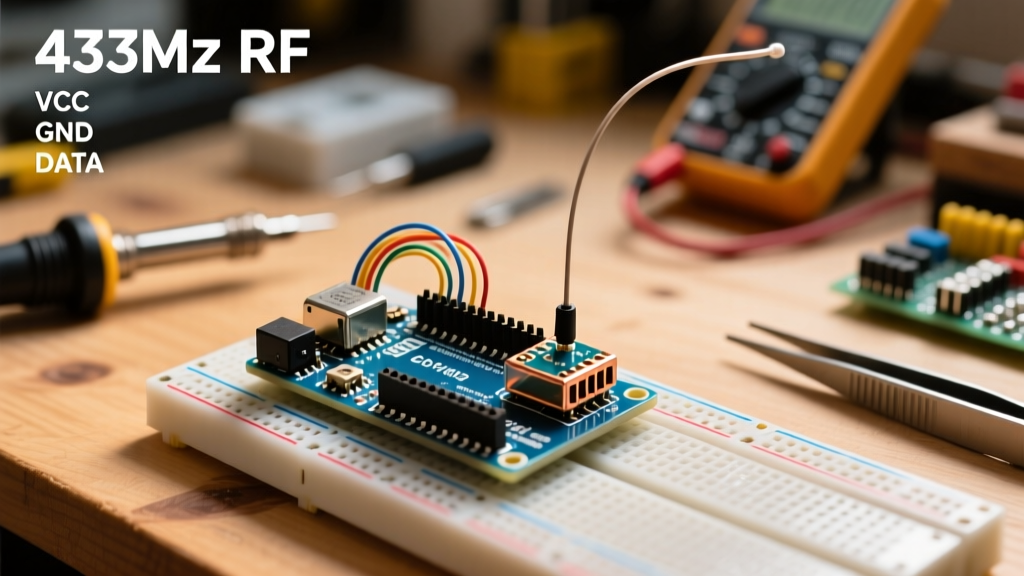
- Transmitter Antenna: Solder a 17.3cm piece of 22 AWG solid-core copper wire to the ANT pad on the FS1000A. Keep it perfectly straight and perpendicular to the ground plane.
- Receiver Antenna: Solder an identical 17.3cm wire to the MX-05V ANT pad.
Warning on Coil Antennas: Many 2026 maker kits include pre-wound copper coil (spring) antennas. While physically compact, these coils have a very high Q-factor and narrow bandwidth. If the manufacturer's winding tolerance is off by even a few millimeters, the resonant frequency shifts outside the 433MHz band, reducing range by up to 80%. Always prefer a straight wire whip for debugging. For deeper physics on quarter-wave antennas, refer to the Texas Instruments Antenna Selection Quick Guide.
Phase 3: Software, Baud Rates, and RadioHead
Raw 433MHz ASK/OOK transmission is essentially turning a digital pin HIGH and LOW. Without a preamble, synchronization headers, and Cyclic Redundancy Checks (CRC), the receiver will interpret ambient RF noise as valid data. Never write your own raw OOK bit-banging code; use the industry-standard RadioHead Library and its RH_ASK driver.
Baud Rate Mismatches and Speed Reductions
The default speed for RH_ASK is 2000 bits per second (bps). In environments with a high noise floor (e.g., near LED drivers, switching power supplies, or Wi-Fi routers), 2000 bps can result in high packet loss. Dropping the baud rate increases the duration of each bit, making it easier for the receiver's AGC to lock onto the signal.
#include <RH_ASK.h>
RH_ASK driver(1200, 11, 12, 10); // Speed reduced to 1200 bps
void setup() {
    if (!driver.init()) Serial.println('RF Init Failed');
}
Critical Note: Both the transmitter and receiver sketches must be initialized with the exact same baud rate. A mismatch will result in the receiver printing garbled ASCII characters because the bit-sampling windows are misaligned.
Interrupt Conflicts with SoftwareSerial
If your Arduino sketch uses SoftwareSerial to communicate with a GPS module or cellular modem while simultaneously receiving RF data, your RF link will intermittently fail. The Arduino SoftwareSerial library disables global interrupts while listening for incoming serial bytes. Because RH_ASK relies on Timer1 interrupts to sample the incoming RF data bits, disabling interrupts causes the RF library to miss bits, fail the CRC check, and silently drop the packet.
The Fix: Use Hardware Serial (pins 0 and 1) for your secondary device, or use an Arduino Mega which has multiple hardware serial ports. If you must use SoftwareSerial, ensure you are not calling listen() on the software port while expecting an incoming RF packet.
Phase 4: Logic Analyzer Debugging
When the serial monitor yields nothing, you must verify if the receiver is actually demodulating a signal. Connect a logic analyzer (like a Saleae Logic Pro or a $10 clone) to the DATA pin of the MX-05V receiver.
- Set the sample rate to at least 1 MHz.
- Trigger on the rising edge of the DATA pin.
- Transmit a known payload (e.g., the string 'HELLO').
- Capture the waveform. You should see the RadioHead preamble (a series of alternating 1s and 0s) followed by the payload bytes encoded in PWM-like pulse widths.
If you see random, chaotic pulses of varying widths when no transmitter is active, you are looking at environmental RF noise. If you see a clean preamble but no payload, your antenna is slightly detuned, or the distance is pushing the limits of the receiver's signal-to-noise ratio (SNR).
Diagnostic Troubleshooting Matrix
| Symptom | Probable Cause | Targeted Fix |
|---|---|---|
| Serial monitor outputs random garbage characters | Baud rate mismatch or 3.3V power on MX-05V | Verify RH_ASK speed matches on both ends; ensure 5.0V to receiver VCC. |
| Works on desk, fails at 5 meters | Transmitter voltage starvation or missing antenna | Supply FS1000A with 12V; solder 17.3cm straight wire antennas. |
| Intermittent packet loss (CRC failures) | SoftwareSerial interrupt blocking | Move debug/comms to Hardware Serial; lower RF speed to 1200 bps. |
| Receiver DATA pin stuck HIGH or LOW | AGC latched due to power spike or short | Cycle power to receiver; verify DATA pin is not shorted to VCC/GND. |
Frequently Asked Questions
Can I use a telescopic antenna instead of a straight wire?
Yes, but telescopic antennas often have poor electrical contact at the base joints, introducing resistance that detunes the circuit. If you use one, ensure it is extended to exactly 17.3cm and solder the base directly to the ANT pad rather than relying on a friction fit.
Why does my RF link fail when I turn on a nearby LED strip?
Cheap WS2812B or generic LED strip power supplies emit massive amounts of electromagnetic interference (EMI) in the 400MHz-500MHz range. This raises the noise floor, blinding the MX-05V receiver's AGC. Move the receiver away from the LED power supply, or add a 100µF electrolytic capacitor across the receiver's VCC and GND pins to filter out power rail noise.
Is the 433MHz band legal to use everywhere?
The 433MHz ISM band is heavily regulated. It is legal for low-power, unlicensed use in Europe and parts of Asia (Region 1). However, in the United States and Canada (Region 2), the 433MHz band is restricted, and the legal ISM band is 315MHz. Using 433MHz modules in North America can technically violate FCC/ISED regulations, though enforcement on low-power hobbyist gear is rare. Always verify your local spectrum allocation.