
The Resolution Bottleneck in Standard Maker Workflows
When prototyping sensor networks or data logging systems, most developers rely on the default 5V or 3.3V analog reference provided by the microcontroller's onboard voltage regulator. While this approach is sufficient for basic potentiometer readings or rough battery voltage monitoring, it creates a severe resolution bottleneck when interfacing with low-voltage, high-precision sensors like thermocouples, strain gauges, or current shunts. In 2026, as edge-computing nodes demand higher fidelity data for local machine learning inference, squeezing every bit of resolution out of your microcontroller's Analog-to-Digital Converter (ADC) is a critical workflow optimization.
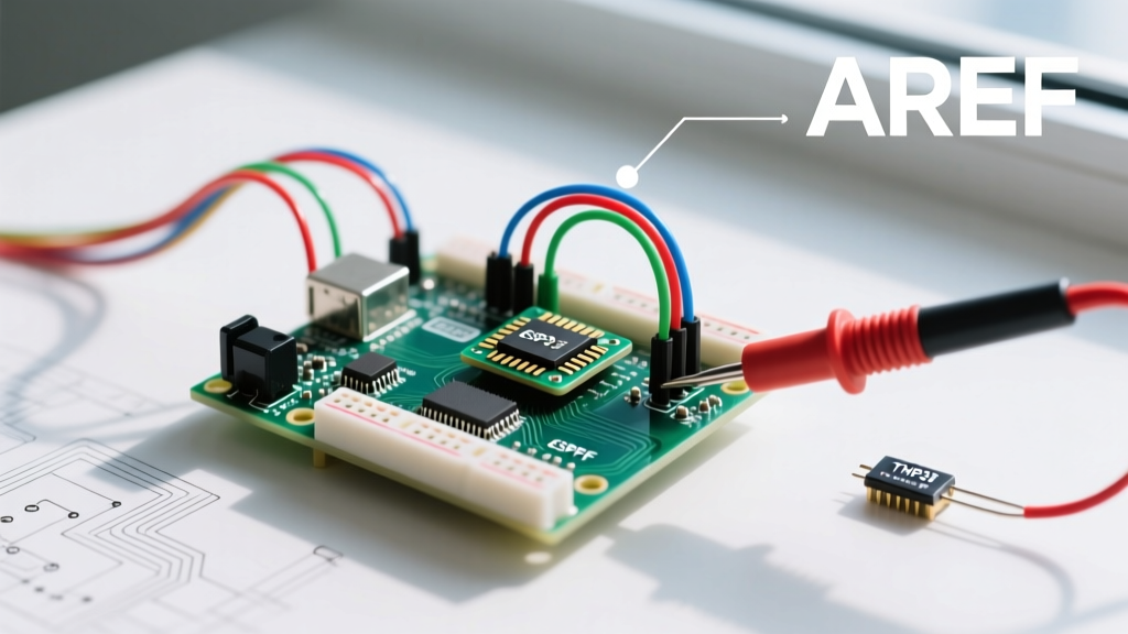
This is where the AREF Arduino pin (Analog Reference) becomes an indispensable tool. By feeding a precision external voltage reference into the AREF pin, you can dynamically scale the ADC's measurement window, effectively multiplying your resolution without upgrading to a more expensive microcontroller or adding an external I2C ADC module.
Quantifying the Resolution Gain
The standard ATmega328P (found in the Uno R3 and Nano) features a 10-bit ADC, yielding 1,024 discrete steps. The voltage represented by each step is entirely dependent on your reference voltage. Below is a comparison of how different reference configurations impact your data acquisition workflow.
| Reference Configuration | Reference Voltage | ADC Step Size (Resolution) | Best Use Case |
|---|---|---|---|
| Default (AVcc) | 5.0V | 4.88 mV | Basic 5V sensor prototyping |
| Internal | 1.1V | 1.07 mV | Internal VCC measurement, very low voltage sensors |
| External (LM4040) | 2.048V | 2.00 mV | Optimized 0-2V industrial sensors |
| External (REF3033) | 3.3V | 3.22 mV | High-precision 3.3V systems with noisy USB power |
By switching from a noisy 5V USB default to a precision 2.048V external reference, you not only halve your step size (improving resolution by over 100%), but you also eliminate the switching noise introduced by the computer's USB power supply.
Hardware Workflow: Designing the AREF Circuit
Optimizing your hardware workflow means moving away from relying on the microcontroller's internal power rails for measurement baselines. To implement a robust external AREF, you must select a dedicated voltage reference IC and condition the signal properly.
Selecting the Right Voltage Reference IC
- LM4040AIZ-2.048 (Shunt Reference): Priced around $1.20, this is the workhorse for 5V Arduino systems. It requires a bias resistor but provides an incredibly stable 2.048V output that maps perfectly to binary math (2.048V / 1024 = exactly 2.0mV per step).
- REF3033AIDBZR (Series Reference): Priced around $2.15, this is ideal for 3.3V systems (like the Arduino Nano 33 IoT or Zero). It draws only 15µA of quiescent current, making it perfect for battery-operated edge nodes.
The Decoupling Protocol
A precision reference IC is only as good as its decoupling network. According to Texas Instruments' voltage reference design guidelines, high-frequency noise must be shunted to ground before it reaches the ADC sample-and-hold capacitor. Your workflow must include the following passive components placed within 5mm of the AREF pin:
- A 100nF X7R ceramic capacitor directly between the AREF pin and GND to handle high-frequency transients.
- A 10µF low-ESR tantalum capacitor in parallel to provide a bulk charge reservoir for the ADC's internal switching capacitor during the sampling phase.
Software Workflow: Safe IDE Configuration
Mishandling the AREF pin in software is the fastest way to permanently destroy an ATmega328P. If you apply an external voltage to the AREF pin while the software is still configured to use the internal 5V or 1.1V reference, you will short-circuit the internal reference op-amp, leading to thermal runaway and silicon death.
Critical Workflow Rule: Always execute theanalogReference()function before you attempt anyanalogRead()operations, and ensure your hardware is wired correctly before uploading the sketch. The official Arduino language reference explicitly warns against this back-biasing failure mode.
Implementation Code
Here is the optimized setup sequence for an external 2.048V reference on an AVR-based board:
// Define external reference for ADC scaling
const float V_REF = 2.048;
const int ADC_STEPS = 1024;

void setup() {
  Serial.begin(115200);

  // CRITICAL: Set reference to EXTERNAL before reading
  analogReference(EXTERNAL);

  // Dummy read to initialize the ADC MUX and charge S/H capacitor
  analogRead(A0);
  delay(10);
}

void loop() {
  int rawAdc = analogRead(A0);
  float preciseVoltage = (rawAdc * V_REF) / ADC_STEPS;

  Serial.print("Sensor Voltage: ");
  Serial.println(preciseVoltage, 4);
  delay(100);
}
Advanced Optimization: Eradicating ADC Noise
Even with a pristine AREF signal, your workflow may still yield jittery data if you ignore the microcontroller's internal architecture. The Microchip ATmega328P datasheet outlines several advanced techniques to optimize the analog reading pipeline.
1. The Dummy Read Technique
When switching between different analog pins (e.g., reading A0, then A1), the internal multiplexer (MUX) needs time to settle, and the sample-and-hold (S/H) capacitor must charge to the new voltage level. If your sensor has a high output impedance (>10kΩ), the first reading after a MUX switch will almost always be corrupted by the previous pin's voltage. Workflow fix: Always perform and discard a "dummy read" on the new pin before recording the actual data.
2. ADC Noise Reduction Sleep Mode
The digital clock signals inside the ATmega328P generate electromagnetic interference that couples into the analog domain. For ultra-precision workflows, you can put the CPU to sleep in 'ADC Noise Reduction' mode. This halts the CPU, I/O clocks, and timers, but leaves the ADC active. The ADC triggers, completes the conversion in a silent electrical environment, and wakes the CPU via an interrupt.
Troubleshooting Matrix: Common AREF Failures
When integrating external references into your PCB or breadboard workflow, use this matrix to quickly diagnose anomalous data.
| Symptom | Root Cause | Workflow Correction |
|---|---|---|
| All analog reads return 1023 | AREF pin is floating or reference IC lacks bias current. | Verify LM4040 bias resistor (typically 4.7kΩ to 5V). |
| Readings are stable but mathematically offset | Using 1.1V internal math with 2.048V hardware. | Update V_REF constant in code to match hardware. |
| High-frequency jitter (±15 steps) | Missing high-frequency decoupling on AREF. | Add 100nF ceramic cap directly to AREF and GND pins. |
| Chip gets hot, AREF measures ~3.2V | Internal reference shorted against external voltage. | Replace MCU; enforce analogReference(EXTERNAL) in setup. |
Conclusion: Elevating Edge-Node Fidelity
Mastering the AREF Arduino pin transitions your projects from hobbyist prototypes to reliable, industrial-grade data acquisition systems. By investing $2 in a precision voltage reference, applying proper decoupling, and adhering to strict software safety protocols, you optimize your entire sensor workflow. You eliminate the need for expensive external ADCs, reduce calibration time, and ensure that the data feeding your edge algorithms is as clean and precise as the physical phenomena you are measuring.