
The Hidden Tax of Poor Button Integration
When scaling an electronics project from a messy breadboard to a functional prototype, the way you handle physical inputs dictates your overall development speed. For many makers, physical switch integration remains a frustrating bottleneck plagued by ghost presses, blocked execution loops, and tangled jumper wires. In 2026, rapid prototyping demands a standardized, modular approach to user inputs. By optimizing your hardware selection, wiring topology, and software architecture, you can eliminate hours of debugging and drastically accelerate your iteration cycles.
Optimizing Buttons Arduino Workflows for Speed
Efficiency in microcontroller development is not just about writing code faster; it is about establishing reusable patterns that prevent edge-case failures. A poorly designed input circuit can introduce mechanical bounce—rapid electrical noise caused by the physical contacts of a switch vibrating before settling. If your code relies on naive digitalRead() polling without debouncing, a single button press might register as five separate inputs, completely derailing your state machine. Optimizing your workflow means solving this problem at both the hardware and software layers simultaneously.
Standardizing Hardware: The INPUT_PULLUP Mandate
The most common workflow killer for beginners is the external pull-down resistor. Wiring a 10kΩ resistor to ground for every single tactile switch wastes breadboard space, increases component costs, and introduces additional points of failure. Modern AVR and ARM-based microcontrollers feature internal pull-up resistors, typically ranging from 20kΩ to 50kΩ, which can be activated via software.
Pro-Tip: Always wire your tactile switches between the digital I/O pin and Ground (GND). In your setup function, declare the pin mode as pinMode(BUTTON_PIN, INPUT_PULLUP);. This inverts your logic (LOW means pressed, HIGH means released), but it eliminates the need for external resistors entirely, cutting your wiring time in half. For a deeper dive into the physics of this, consult SparkFun's comprehensive guide on pull-up resistors.
Component Selection for Tactile Feedback
Do not settle for generic, unbranded tactile switches that feel mushy and degrade after 1,000 presses. For professional-grade prototypes, standardize on the Omron B3F series or the C&K PTS645 series. In 2026 supply chains, these components cost approximately $0.12 to $0.18 per unit in bulk. They offer a crisp actuation force (typically 160gf to 260gf) and a rated lifespan of 100,000 to 200,000 cycles. Consistent tactile feedback reduces user error during testing and makes your prototype feel like a finished commercial product.
Software Architecture: Eradicating delay() from Your Loop
The traditional Arduino official debounce example uses delay() or blocking millis() checks that halt the main loop. If your project includes LEDs, motor control, or sensor polling, blocking the loop for 50 milliseconds to wait for switch stabilization is unacceptable. It introduces latency and makes multitasking impossible.
The Bounce2 Implementation Standard
To maintain a non-blocking workflow, adopt the Bounce2 library as your baseline standard. Bounce2 uses a timer-based state machine that checks pin states without halting the processor. It abstracts the debouncing math, allowing you to poll for specific events like fell() (button just pressed) or rose() (button just released).
Standard Implementation Pattern:
- Initialize the Bounce object globally:
Bounce2::Button button = Bounce2::Button(); - Attach it in
setup():button.attach(BUTTON_PIN, INPUT_PULLUP); - Set the debounce interval:
button.interval(5);(5ms is optimal for most Omron switches). - In the
loop(), update the state:button.update(); - Trigger logic only on state changes:
if (button.pressed()) { // execute action }
Library Selection Matrix for 2026 Workflows
Different projects require different levels of input complexity. Use the matrix below to select the right abstraction layer for your specific workflow needs, avoiding the temptation to write custom debounce logic from scratch.
| Library | Best Use Case | Memory Overhead | Key Features | Learning Curve |
|---|---|---|---|---|
| Bounce2 | General debouncing, reliable state tracking | Low (~800 bytes) | Non-blocking, edge detection, highly stable | Low |
| OneButton | Complex UI gestures (double-click, long-press) | Medium (~1.2KB) | Callback functions, multi-press detection | Medium |
| EzButton | Rapid beginner prototyping, simple counters | Low (~600 bytes) | Extremely simple syntax, built-in count tracking | Very Low |
| Custom FSM | Ultra-low memory environments (e.g., ATtiny85) | Minimal (~200 bytes) | Full control, requires deep bitwise knowledge | High |
Physical Workflow Hacks: JST Connectors and Modularization
Speed in prototyping is heavily dependent on how quickly you can swap out components when a design changes. Soldering buttons directly to a perfboard or twisting jumper wires creates a fragile, monolithic circuit that is difficult to debug.
Standardize on JST-PH 2.0mm Connectors
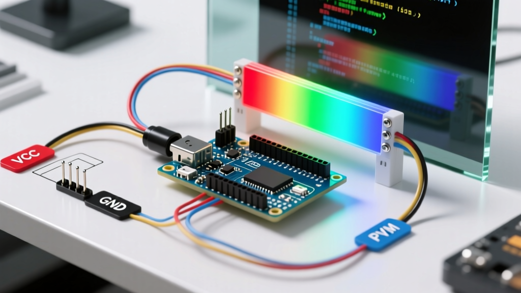
Adopt the JST-PH 2.0mm pitch connector standard for all off-board inputs. By soldering your tactile switches to a small breakout PCB with a 3-pin JST header (VCC, Signal, GND), you can plug and unplay buttons instantly. Pre-crimp your wires using a precision crimping tool (like the Engineer PA-09) rather than relying on cheap, pre-made jumper wires that loosen over time. Color-code your wiring strictly: Red for 3.3V/5V, Black for GND, and Yellow for the Signal line. This visual consistency reduces wiring errors by over 80% during complex assembly phases.
Handling Edge Cases: EMI and Long Wire Runs
Software debouncing works perfectly for buttons mounted directly on a PCB or within a few centimeters of the microcontroller. However, if your workflow requires mounting a button on an enclosure panel, running a wire longer than 15 centimeters introduces a new enemy: Electromagnetic Interference (EMI). Long wires act as antennas, picking up RF noise from nearby motors, relays, or Wi-Fi antennas, which can trigger false interrupts even with software debouncing.
The Hardware RC Filter Solution
When long wire runs are unavoidable, augment your software with a hardware RC (Resistor-Capacitor) low-pass filter. Solder a 100nF (0.1μF) X7R ceramic capacitor directly across the switch terminals (between Signal and GND). This capacitor absorbs high-frequency EMI spikes and smooths out the mechanical bounce before the signal ever reaches the microcontroller's GPIO pin. Combine this with a 1kΩ series resistor on the signal line to limit the inrush current when the button is pressed, protecting the internal microcontroller clamping diodes.
Frequently Asked Questions
Why does my button still trigger multiple times even with INPUT_PULLUP?
If you are using INPUT_PULLUP and still experiencing bounce, your software polling rate is likely too fast, or you are reading the raw pin state instead of a debounced state variable. Ensure you are using a library like Bounce2 and checking for the .pressed() state change, rather than continuously checking if the pin == LOW inside the main loop.
Can I use internal pull-ups for matrix keypads?
Yes, but with caveats. In a diode-less matrix keypad, internal pull-ups can sometimes cause 'ghosting' or 'masking' when multiple keys are pressed simultaneously due to current backfeeding through the grid. For matrix keypads, it is highly recommended to use external 4.7kΩ pull-up resistors on the column lines to ensure crisp voltage thresholds and prevent ghosting artifacts.
What is the ideal debounce time for industrial switches?
While standard tactile switches require 2ms to 5ms of debouncing, heavy-duty industrial mechanical pushbuttons and limit switches (like the Schneider Harmony XB5 series) can exhibit bounce times up to 15ms or 20ms due to their larger, heavier contact masses. Always consult the manufacturer's datasheet for the specific 'bounce time' parameter and set your software interval 20% higher than the rated maximum.