
The Hidden Danger of Running an Arduino on 12V
When makers deploy an arduino on 12v power rails—typically in automotive diagnostics, solar tracking systems, or 12V LED lighting controllers—the initial setup seems straightforward. Plug the 12V barrel jack or VIN pin into the board, and the onboard linear regulator steps it down to a clean 5V. However, this simplicity masks a severe thermodynamic and electrical vulnerability. According to the Arduino Official Power Documentation, the recommended input voltage is 7V to 12V, but operating continuously at the 12V absolute maximum exposes the microcontroller to chronic thermal throttling, brownout resets, and catastrophic voltage spike failures.
This diagnostic guide dissects the exact failure modes of 12V Arduino deployments, providing actionable multimeter readings, root-cause analysis, and hardware-level solutions to ensure your project survives outside the laboratory.
The Thermodynamics of Linear Regulation
To diagnose 12V errors, you must first understand how the Arduino Uno R3 (and similar boards like the Mega 2560) handles voltage. These boards utilize an NCP1117ST50T3G linear regulator. Unlike switching regulators, linear regulators dissipate excess voltage as pure heat. The power dissipation formula is:
P_dissipated = (V_in - V_out) × I_load
If you supply 12V and your circuit (microcontroller, sensors, and a small display) draws 100mA (0.1A):
- Voltage Drop: 12V - 5V = 7V
- Power Dissipated: 7V × 0.1A = 0.7 Watts
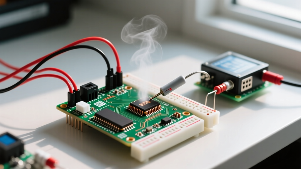
The SOT-223 package of the NCP1117 has a junction-to-ambient thermal resistance of approximately 50°C/W. A 0.7W dissipation causes the silicon junction temperature to rise by 35°C above ambient. In a sealed project enclosure at 30°C ambient, the regulator hits 65°C. Push the current draw to 150mA, and the junction easily exceeds 105°C, triggering the regulator's internal thermal shutdown protection.
Diagnostic Matrix: Identifying Your 12V Failure Mode
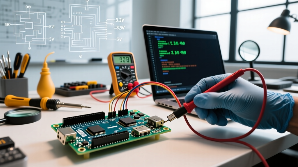
Use the following matrix to correlate your board's physical symptoms with multimeter readings and isolate the root cause of your 12V power errors.
| Observed Symptom | Multimeter Reading (at 5V Pin) | Root Cause | Diagnostic Action |
|---|---|---|---|
| Regulator too hot to touch (>60°C) | Drops from 5.0V to 4.2V under load | Thermal throttling of NCP1117 | Measure total current draw; reduce peripheral load |
| Random reset loops / Watchdog timeouts | Transient dips to 3.8V during actuator switching | Brownout Detection (BOD) triggering | Scope the 5V rail for high-frequency voltage sag |
| USB disconnects when 12V is applied | 5V rail reads 5.2V or higher | Backfeeding through USB or 5V pin | Verify 5V pin is not externally powered alongside VIN |
| Dead board / Short circuit on VIN | 0V on 5V pin; continuity to GND | Catastrophic silicon junction failure | Inspect for automotive load dump or reversed polarity |
Failure Mode 1: Thermal Shutdown and Reset Loops
The most common error when running an arduino on 12v is the "phantom reset." Your sketch runs perfectly for 14 minutes, then abruptly restarts. This is rarely a software bug. When the NCP1117 reaches its thermal limit (typically around 150°C junction temperature), it shuts off the output to prevent melting. The ATmega328P loses power, the capacitors discharge, and once the regulator cools by a few degrees, it powers back on. This creates an endless, frustrating reset loop. The SparkFun Voltage Regulator Tutorial emphasizes that linear regulators are entirely unsuited for high-draw applications when the input-to-output differential exceeds 5V.
Failure Mode 2: The Automotive "12V" Myth and Load Dumps
If your 12V source is a car battery or an automotive fuse tap, you are not actually supplying 12V. A running vehicle's alternator outputs between 13.8V and 14.4V. At 14.4V, your thermal dissipation increases by 20%. Worse, automotive electrical systems are incredibly noisy. When a high-inductance load (like a radiator fan or AC clutch) is switched off, it generates a transient voltage spike known as a "load dump."
Under the ISO 7637-2 standard (Pulse 2a), these spikes can reach 40V to 80V for tens of milliseconds. The NCP1117 has an absolute maximum input voltage rating of 20V. A single load dump event will cause the regulator's internal silicon to avalanche, permanently shorting the input to the output and sending 14V+ directly into your 5V microcontroller, instantly destroying it.
Failure Mode 3: Ground Loops and ADC Noise
When powering an Arduino from a 12V switched-mode power supply (SMPS) while simultaneously reading analog sensors, you may notice erratic analogRead() values. Cheap 12V SMPS units often have high common-mode noise and poor isolation. This noise couples into the Arduino's ground plane, artificially elevating the analog reference voltage and resulting in jittery sensor data.
Proven Solutions for Stable 12V Operation
To eliminate these errors, you must abandon the onboard linear regulator for high-draw or hostile environments. Below are the three most reliable architectural fixes.
1. Implement a Step-Down (Buck) Converter
Switching buck converters efficiently step down 12V to 5V with minimal heat generation (often >90% efficiency). You can feed the resulting 5V directly into the Arduino's 5V pin, entirely bypassing the flawed NCP1117.
- MP1584EN Modules ($2 - $4): Ubiquitous and cheap, but require manual adjustment via a tiny potentiometer. Diagnostic Tip: Always set the output voltage with a multimeter before connecting it to your Arduino. Cheap clones often ship with the potentiometer set to 12V, which will fry your board.
- Pololu D24V50F5 ($14 - $16): A premium, fixed 5V output switching regulator capable of delivering up to 5A. It features excellent ripple rejection and built-in short-circuit protection. Refer to the Pololu Step-Down Voltage Regulator Guide for proper wiring and capacitor placement to minimize EMI.
2. The Drop-In Switching Replacement (Recom R-785.0)
If you want to keep the power routing on the Arduino board itself, you can desolder the factory NCP1117 and solder in a Recom R-785.0-1.0 switching regulator. Priced around $9.00, it shares the same pinout as the 7805 linear standard but operates as a high-efficiency switcher. It handles inputs up to 34V and outputs a clean 5V at 1A without requiring a heatsink.
3. Optocoupling and Transient Suppression (Automotive Only)
If deploying in a vehicle, a buck converter alone is not enough. You must protect the input stage. Install a TVS (Transient Voltage Suppression) diode, such as the SMAJ15A, in parallel with your 12V input to clamp load dump spikes. Follow this with a polyfuse and a Schottky diode (e.g., 1N5819) for reverse-polarity protection before the voltage reaches your buck converter.
CRITICAL WARNING: The 5V Pin Bypass Trap
When feeding 5V from an external buck converter directly into the Arduino's 5V pin, you must never plug in the USB cable simultaneously. The Arduino's onboard USB polyfuse and power-path management IC (often an LM358 comparator circuit) are not designed to arbitrate between a strong external 5V source and a 5V USB host. Backfeeding 5V into the USB port can damage your host computer's motherboard. Always use a USB isolator or physically disconnect the external 5V when uploading sketches via USB.
Summary Checklist for 12V Deployments
Before sealing your project enclosure, run through this diagnostic checklist to ensure your 12V architecture is bulletproof:
- Measure True Input Voltage: Verify if your "12V" source is actually 14.4V (automotive) or has high ripple (cheap wall adapters).
- Calculate Total Current: Sum the mA draw of the MCU, sensors, and relays. If it exceeds 80mA, do not use the onboard VIN/barrel jack linear regulator.
- Add Bulk Capacitance: Place a 470µF electrolytic capacitor and a 0.1µF ceramic capacitor near the input of your external buck converter to handle transient motor/relay startup currents.
- Verify Grounding: Ensure all 12V loads (like LED strips or motors) share a common ground with the Arduino, but keep their high-current return paths physically separated from the Arduino's low-current analog ground traces to prevent ADC noise.
By understanding the thermal and electrical limitations of the Arduino's native power circuitry, you can transition from constant troubleshooting to deploying robust, field-ready microcontroller systems.