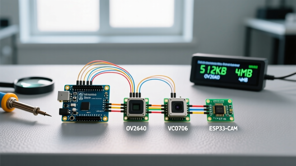

The SRAM Bottleneck: Why Most Camera Modules Fail on Arduino Uno
When makers first attempt to figure out how to interface Arduino with a camera, the most common point of failure is not the wiring—it is the microcontroller's memory architecture. A standard VGA image (640x480 pixels) captured in RGB565 format requires 614,400 bytes (600 KB) of RAM. The ATmega328P chip on an Arduino Uno possesses a mere 2 KB of SRAM. Attempting to stream raw pixel data directly from a parallel camera module into an Uno will result in immediate memory overflow and system crashes.
To successfully integrate vision into your projects, you must match the camera module's interface and buffering capabilities to your specific microcontroller. In this 2026 compatibility guide, we break down the three primary hardware pathways: TTL Serial JPEG modules, SPI-based FIFO cameras, and native DCMI integrations.
Microcontroller vs. Camera Compatibility Matrix
| Microcontroller | SRAM / PSRAM | Best Camera Interface | Recommended Module | Estimated Cost (2026) |
|---|---|---|---|---|
| Arduino Uno (ATmega328P) | 2 KB SRAM | UART (Serial JPEG) | VC0706 TTL Serial JPEG | $25 - $30 |
| Arduino Mega (ATmega2560) | 8 KB SRAM | UART or SPI (FIFO) | Arducam Mini 2MP (OV2640) | $15 - $20 |
| ESP32 (WROOM-32) | 520 KB SRAM + 4MB PSRAM | 8-bit DCMI (Native) | ESP32-CAM (Integrated OV2640) | $8 - $12 |
| Raspberry Pi Pico (RP2040) | 264 KB SRAM | SPI or PIO (Parallel) | Arducam Pico4ML / OV5647 | $12 - $18 |
Method 1: TTL Serial JPEG Cameras (VC0706) for ATmega Boards
If you are strictly bound to an Arduino Uno or Nano and need to capture still images, the Adafruit TTL Serial JPEG Camera (based on the VC0706 chipset) is your most reliable option. Instead of sending raw pixel data, the VC0706 handles image compression internally and outputs a standard JPEG file stream over UART (TX/RX pins).
Wiring and Voltage Translation
The VC0706 operates at 3.3V logic and requires a stable 5V power input for its onboard regulator. However, the Arduino Uno's hardware serial pins (D0 and D1) output 5V logic. Feeding 5V into the VC0706's RX pin will eventually degrade or destroy the module's silicon.
- Power: Connect the camera's 5V pin to the Arduino's 5V rail. Do not use the 3.3V pin, as the camera's peak draw during compression can spike to 120mA, exceeding the Arduino's onboard LP2985-33 LDO thermal limits.
- Logic Level Shifting: Use a bidirectional logic level converter (like the BSS138 MOSFET-based breakouts) or a simple voltage divider (2.2kΩ and 3.3kΩ resistors) on the Arduino TX to Camera RX line. The Camera TX to Arduino RX line is generally safe, as 3.3V is recognized as a valid HIGH by the ATmega328P.
- Library: Utilize the Adafruit VC0706 Serial Camera library to handle the proprietary UART handshake protocols.
Method 2: SPI Cameras with FIFO Buffers (Arducam OV2640)
For applications requiring higher frame rates, raw sensor access, or custom compression, the Arducam Mini 2MP Plus (OV2640) is the industry standard for SPI-based Arduino interfacing. The secret to making this work on low-SRAM boards is the onboard FIFO (First-In-First-Out) memory buffer chip (usually an AL422B).
How the FIFO Solves the Memory Crisis
When you trigger a capture, the OV2640 sensor writes the entire image frame directly into the AL422B FIFO chip, which holds up to 384KB of data. The Arduino can then leisurely read this data byte-by-byte over the SPI bus, process it, and write it to an SD card without needing to hold the image in its own 2KB SRAM. According to Arduino's official SPI documentation, the SPI bus can handle the throughput required to empty the FIFO in roughly 1.5 seconds at standard 8MHz clock speeds.
Expert Troubleshooting Tip: If your Arducam module returns a '0x00' or '0xFF' continuously during the SPI test, your chip select (CS) pin is likely floating or misconfigured. On an Uno, CS must be tied to Pin 10 (even if you use Pin 4 for the SD card CS) to force the ATmega328P into SPI Master mode.
Method 3: Native DCMI via ESP32-CAM (The Modern Standard)
While the prompt asks how to interface Arduino with a camera, it is vital to address the architectural shift in the maker space. In 2026, attempting to stream live video using an ATmega-based Arduino is considered an anti-pattern. The ESP32-CAM board (featuring the ESP32-S chip and an integrated OV2640) utilizes a native 8-bit DCMI (Digital Camera Memory Interface) hardware peripheral.
This allows the ESP32 to pull raw pixel data directly into its PSRAM at hardware speeds, enabling 30 FPS VGA streaming over Wi-Fi. If your project requires computer vision, OpenMV integration, or live RTSP streaming, bypass the traditional Arduino Uno entirely and program the ESP32-CAM using the Arduino IDE's ESP32 core.
Critical Hardware Failure Modes & Edge Cases
Interfacing image sensors with microcontrollers introduces several electrical engineering pitfalls that rarely appear in basic tutorials. Watch out for these specific failure modes:
1. The I2C Configuration Bottleneck
Almost all raw camera modules (OV7670, OV2640, OV5647) use I2C (SCCB protocol) for register configuration, but SPI or Parallel for pixel data transfer. The I2C bus must be initialized and the sensor configured before the SPI/DCMI capture begins. If your I2C pull-up resistors are too weak (e.g., 10kΩ on a noisy 5V rail), the initial handshake will fail silently, and the camera will output pure static.
2. Voltage Translation for 3.3V Sensors
Modern image sensors are strictly 3.3V or 2.8V logic. Connecting an Arduino Mega's 5V SPI pins directly to an OV2640 will fry the sensor's I/O ring. For high-speed SPI lines, simple resistor dividers introduce too much capacitance and ruin the signal edges. Instead, use a dedicated voltage translation IC like the Texas Instruments SN74LVC8T245. As detailed in TI's Voltage Translation Application Note, dedicated translators maintain the fast edge rates required for SPI clocks running above 4MHz.
3. Power Rail Brownouts During Capture
Image sensors draw a baseline current of ~30mA when idle, but this can spike to 150mA+ during the initial PLL lock and sensor wake-up phase. If you are powering the camera from a shared breadboard power rail with long, thin jumper wires, the voltage drop (V = IR) will cause a brownout, resetting the Arduino mid-capture. Always use a dedicated local 100µF decoupling capacitor across the camera module's VCC and GND pins, and consider a local AMS1117-3.3 LDO regulator placed physically adjacent to the camera module.
Summary Decision Framework
To summarize your hardware selection process:
- Need a simple still image on an Uno? Use the VC0706 Serial JPEG module.
- Need raw data or custom processing on a Mega/Uno? Use the Arducam OV2640 with its FIFO buffer.
- Need live video, Wi-Fi streaming, or AI edge detection? Abandon the ATmega architecture and use an ESP32-CAM programmed via the Arduino IDE.