
Mastering Temperature Detector Arduino Error Diagnosis
Building a reliable temperature detector Arduino system is a foundational milestone for any maker or embedded engineer. However, transitioning from a breadboard prototype to a stable, real-world deployment often exposes hidden hardware flaws, timing mismatches, and power supply anomalies. When your serial monitor spits out impossible values like -127°C, or your analog readings fluctuate wildly, the issue rarely lies in the microcontroller itself. Instead, it points to sensor-specific edge cases, bus contention, or improper decoupling.
In this comprehensive diagnostic guide, we dissect the most frequent failure modes across the three dominant temperature sensing architectures in 2026: 1-Wire digital (DS18B20), analog voltage (TMP36/LM35), and SPI thermocouple interfaces (MAX31855). We will bypass generic advice and dive into exact multimeter measurements, timing parameters, and code-level corrections required to stabilize your readings.
Sensor Architecture & Baseline Specifications
Before troubleshooting, you must understand the electrical baseline of your specific sensor. The market is currently flooded with both genuine silicon and cloned dies, which can exhibit varying parasitic capacitance and timing tolerances. Below is a diagnostic baseline for the most common components used in temperature detector Arduino projects.
| Sensor Model | Interface | Operating Range | Typical 2026 Price (Genuine) | Primary Failure Symptom |
|---|---|---|---|---|
| Maxim DS18B20 | 1-Wire Digital | -55°C to +125°C | $3.50 - $5.50 | Returns 85°C or -127°C |
| Analog Devices TMP36 | Analog Voltage | -40°C to +125°C | $1.80 - $2.50 | Noisy, drifting ±3°C readings |
| MAX31855 (K-Type) | SPI Digital | -200°C to +700°C | $9.00 - $14.00 | Returns NAN or SPI Fault Codes |
Decoding the DS18B20: Phantom Readings and Bus Disconnects
The DS18B20 is the undisputed king of digital temperature sensing, but its 1-Wire protocol is notoriously unforgiving regarding timing and pull-up topology. If your temperature detector Arduino sketch is returning anomalous data, it almost always falls into one of two specific error codes.
The "85°C" Power-On Reset (POR) Trap
If your sensor consistently reads exactly 85°C upon boot or during rapid polling, you are reading the sensor's scratchpad before it has completed its analog-to-digital conversion. According to the Analog Devices DS18B20 datasheet, 85°C is the factory default Power-On Reset value stored in the scratchpad EEPROM.
- The Cause: The microcontroller issues the
Convert Tcommand but immediately reads the scratchpad without waiting for the conversion to finish. At 12-bit resolution, conversion takes up to 750ms. - The Fix: Avoid using blind
delay(750)calls which block your main loop. Instead, implement a non-blocking state machine that checks the sensor'sisConversionComplete()status, or utilize the OneWire library's parasite power strong pull-up mechanism correctly if you are operating without a dedicated VDD line.
The "-127°C" or "-196°F" Phantom Disconnect
A reading of -127°C (or the Fahrenheit equivalent) is not a physical temperature; it is the Dallas/Maxim library's hardcoded error return for a CRC mismatch or a missing device on the bus.
- Missing Pull-Up Resistor: The 1-Wire data line requires a strict 4.7kΩ pull-up resistor to VCC (3.3V or 5V). Without it, the line floats, and the Arduino reads garbage noise. Measure the resistance between your data pin and VCC with a multimeter while the board is powered off; it should read ~4.7kΩ.
- Parasitic Power Failure: If you are using parasitic power mode (VDD tied to GND), the Arduino's GPIO pin cannot source enough current to power the sensor's internal ADC during conversion. You must use a dedicated MOSFET circuit to provide a 'strong pull-up' during the conversion phase, or simply wire the sensor to external VCC.
Eliminating Analog Noise in TMP36 and LM35 Circuits
Analog sensors like the TMP36 output a continuous voltage proportional to temperature (10mV/°C for the TMP36). While conceptually simple, they are highly susceptible to electromagnetic interference (EMI) and power supply ripple, resulting in a temperature detector Arduino setup that fluctuates wildly.
Diagnosing ADC Ripple and Ground Bounce
If your serial plotter looks like a jagged sawtooth wave rather than a smooth curve, your Analog-to-Digital Converter (ADC) is sampling noise. This is often caused by the switching regulators inside USB power banks or the digital noise generated by the ATmega328P's own clock harmonics.
Expert Diagnostic Tip: Never rely on the default 5V USB reference for precision analog sensing. USB VCC can fluctuate between 4.7V and 5.2V, which directly skews your temperature math. Always switch to the internal reference using analogReference(INTERNAL) to lock the ADC to the microcontroller's highly stable 1.1V internal bandgap reference.When utilizing the 1.1V internal reference, your maximum measurable voltage is capped at 1.1V. For a TMP36 (which outputs 0.5V at 0°C and 1.0V at 50°C), this provides a massive boost in ADC resolution for standard ambient monitoring. For deeper technical implementation of ADC references, consult the official Arduino analogReference() documentation.
Hardware Decoupling Requirements
To stabilize the analog signal at the source, you must implement proper decoupling. Solder a 0.1µF (100nF) ceramic capacitor directly across the VCC and GND pins of the TMP36, as physically close to the sensor's epoxy body as possible. This creates a localized high-frequency charge reservoir, filtering out RF interference picked up by long wire runs. If your wires exceed 1 meter, use shielded twisted-pair (STP) cable and tie the shield to the Arduino ground at one end only to prevent ground loops.
SPI Fault Codes in MAX31855 Thermocouple Interfaces
For high-temperature applications like kilns, 3D printer hotends, or automotive exhaust monitoring, K-type thermocouples paired with a MAX31855 SPI breakout board are the standard. However, SPI communication errors frequently masquerade as sensor failures.
Interpreting the 32-Bit Fault Packet
When a MAX31855 library returns NAN (Not a Number), the chip is actively flagging a hardware fault in the lowest three bits of its 32-bit SPI data packet. You must modify your diagnostic sketch to read and print these specific fault bits:
- Bit D0 (0x01): Open Circuit. The thermocouple wires are broken or disconnected from the terminal block. Check continuity with a multimeter.
- Bit D1 (0x02): Short to GND. The thermocouple junction is physically touching a grounded metal chassis. Ensure the junction is isolated using ceramic beads or high-temp Kapton tape.
- Bit D2 (0x04): Short to VCC. The thermocouple wiring is shorted to a positive voltage source, a common issue in environments with high-voltage AC heating elements nearby.
SPI Bus Contention and Clock Phase
If your temperature detector Arduino shares the SPI bus with an SD card module or an RFID reader, the MAX31855 may fail to initialize. The MAX31855 requires SPI Mode 0 (CPOL=0, CPHA=0) or Mode 3, and it is strictly a read-only device (MISO only). If another device on the bus fails to release the MISO line (tri-state) when its Chip Select (CS) pin is HIGH, the thermocouple data will be corrupted. Always verify that every SPI peripheral on your bus features proper tri-state logic on its MISO output.
The 4-Step Hardware Diagnostic Checklist
When software debugging fails, revert to this systematic hardware verification process to isolate the fault in your temperature detector Arduino circuit.
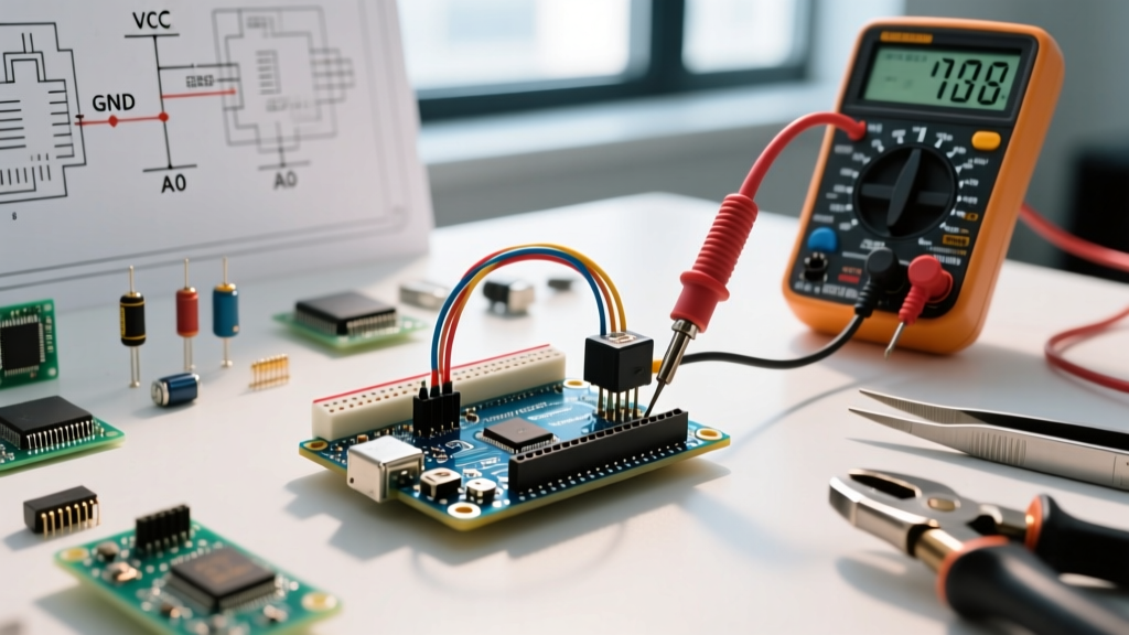
- Verify VCC at the Sensor Pins: Do not measure at the Arduino's 5V pin. Back-probe the actual VCC and GND pins on the sensor breakout board while the circuit is under load. A reading below 4.5V on a 5V digital sensor indicates excessive voltage drop through thin jumper wires or a failing onboard voltage regulator.
- Check the Ground Topology: If you are switching a high-power load (like a Peltier cooler or AC heater) via a relay or MOSFET, the sensor ground must be routed in a 'star topology' directly back to the Arduino's main GND pin. Sharing a ground wire with high-current loads will introduce massive ground bounce, corrupting both 1-Wire and Analog readings.
- Inspect Solder Joints for Thermal Stress: In high-temp environments, lead-free solder joints on the sensor breakout board can develop micro-fractures due to repeated thermal cycling. Visually inspect joints under a magnifying glass for dull, grainy textures indicative of cold joints or thermal fatigue.
- Validate Library Versions: In 2026, legacy forks of the OneWire and Adafruit_MAX31855 libraries may conflict with newer Arduino SAMD and ESP32 core architectures. Ensure you are pulling directly from the official GitHub repositories via the Arduino Library Manager to guarantee hardware-abstraction-layer (HAL) compatibility.
Conclusion
Diagnosing a faulty temperature detector Arduino setup requires moving beyond simple wiring diagrams and understanding the electrical physics of your chosen sensor. Whether you are managing the strict microsecond timing of a 1-Wire DS18B20 bus, filtering analog noise on a TMP36, or decoding SPI fault packets on a MAX31855, the solution almost always lies in proper decoupling, precise pull-up topologies, and stable voltage references. By applying these targeted diagnostic steps, you can transform an unreliable prototype into an industrial-grade temperature monitoring system.
For further reading on analog sensor conditioning, refer to the application notes provided by Analog Devices for the TMP36 series, which detail advanced PCB layout techniques for minimizing EMI in mixed-signal environments.