
The Core Architecture: Why MAX7219 Modules Fail
Integrating a MAX7219 with Arduino is a staple of DIY electronics, powering everything from retro LED matrix clocks to scrolling stock tickers. However, the transition from a single 8x8 module to a cascaded 4-in-1 FC-113 board often introduces severe signal integrity and power delivery issues. In 2026, with the proliferation of 3.3V microcontrollers like the ESP32 and Raspberry Pi Pico, legacy 5V TTL chips like the MAX7219 present unique logic-level challenges that most basic tutorials completely ignore.
This guide bypasses generic wiring diagrams and dives straight into advanced diagnostic procedures. We will address the four most critical failure modes: power brownouts, unresponsive shutdown registers, SPI signal degradation, and logic-level mismatches.
Symptom 1: Flickering, Dimming, and Arduino Brownouts
The most frequent complaint when scaling up to a 4-module FC-113 (32x8 matrix) is severe flickering or the Arduino randomly resetting. This is rarely a software bug; it is a fundamental power delivery failure.
The Multiplexing Current Spike
The MAX7219 multiplexes the display, illuminating one row at a time. According to the official Analog Devices MAX7219 datasheet, a single chip driving 8 LEDs at 20mA per segment draws roughly 160mA. A 4-module board draws up to 640mA in peak bursts. The onboard 5V linear regulator of an Arduino Uno R3 or Nano is typically rated for 800mA absolute maximum, but realistically sustains only 400mA before thermal throttling or voltage droop occurs.
The Fix: Dual-Capacitor Decoupling and External Power
- Inject External Power: Do not power a 4-module board from the Arduino 5V pin. Use a dedicated 5V 2A buck converter or a high-quality USB power bank wired directly to the module's VCC and GND pins.
- Establish Common Ground: You must connect the GND of the external power supply to the GND of the Arduino. Without a shared ground reference, the SPI data lines will float, causing garbage data.
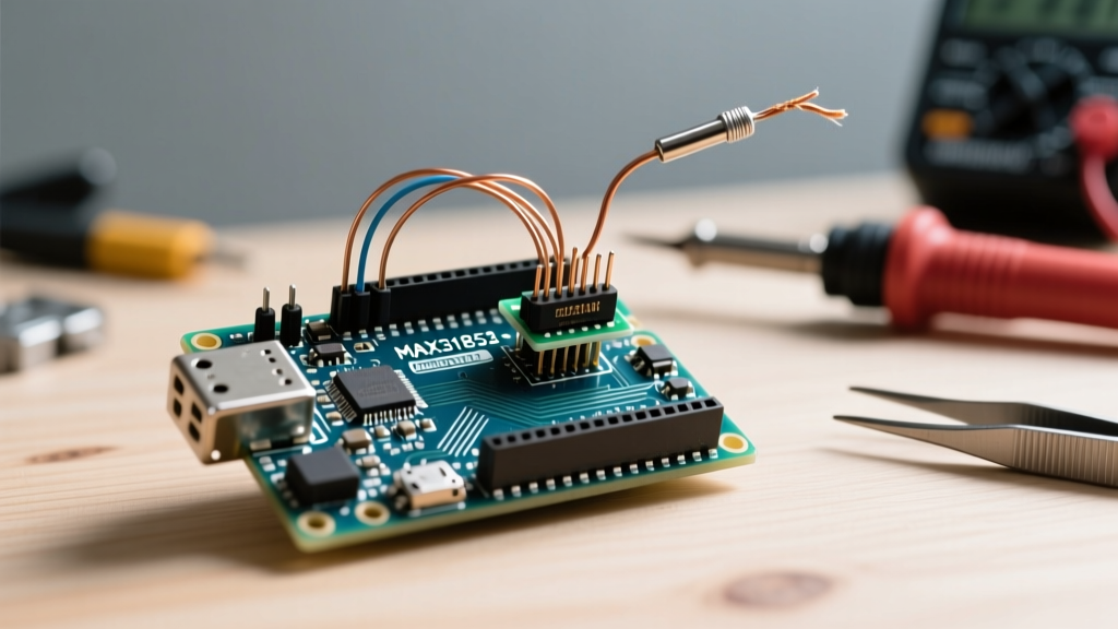
- The Dual-Capacitor Rule: Solder a 10µF electrolytic capacitor and a 0.1µF (100nF) ceramic capacitor directly across the VCC and GND pins on the module's PCB. The ceramic cap handles high-frequency SPI switching noise, while the electrolytic cap buffers the multiplexing current spikes.
Symptom 2: Completely Blank Display (No LEDs)
If your wiring is correct but the matrix remains completely dark, the issue usually lies in the MAX7219's internal registers or the physical CS (Chip Select) line.
Software Shutdown Register
Upon power-up, the MAX7219 defaults to 'Shutdown Mode' to prevent current draw. If your code does not explicitly wake the chip, it will remain blank. If you are using the classic LedControl library, ensure you have the following in your setup() function:
lc.shutdown(0, false); // Wake up display 0
lc.setIntensity(0, 8); // Set brightness (0-15)
Hardware Pin 18 (RSET) Verification
Inspect the physical PCB for the resistor labeled RSET (connected to Pin 18). This resistor programs the internal current sink. A standard 10kΩ resistor yields ~20mA per LED segment. If you purchased a cheap clone module with a 47kΩ or missing resistor, the current will be too low to illuminate the LEDs visibly. Replace it with a 10kΩ through-hole resistor.
Symptom 3: Garbage Data, Ghosting, and Random Pixels
Random LEDs lighting up or 'ghosting' (faint illumination of adjacent pixels) indicates signal integrity degradation on the SPI bus. The Arduino SPI communication protocol pushes data at high frequencies, and long, unshielded Dupont wires act as antennas, picking up electromagnetic interference (EMI).
The ESP32 Logic Level Mismatch (Critical 2026 Update)
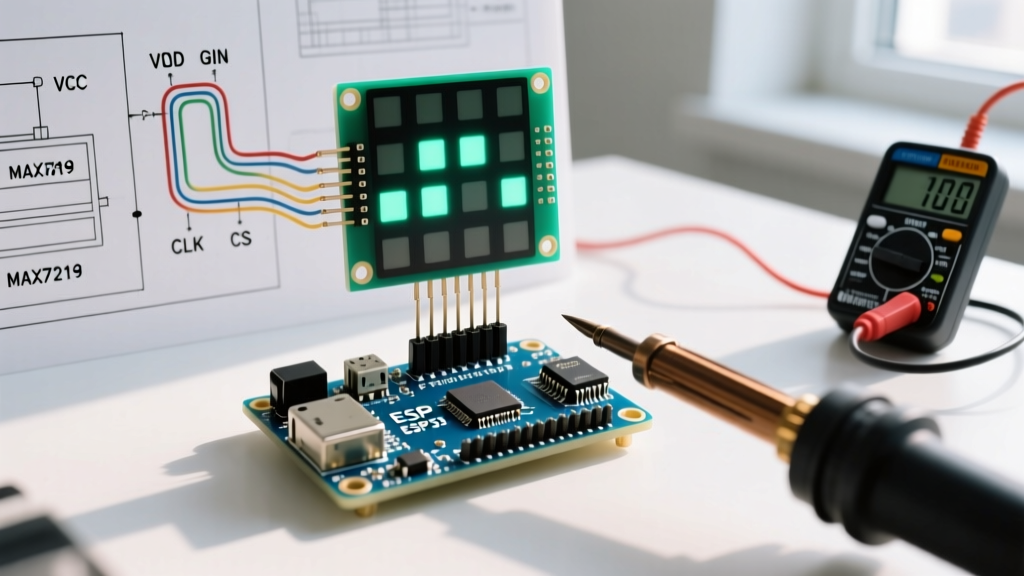
If you are driving a MAX7219 with an ESP32, RP2040, or any 3.3V microcontroller, you will likely experience random noise. The MAX7219 requires a VCC of 4.0V to 5.5V. At 5.0V VCC, the datasheet specifies a minimum Input High Voltage (VIH) of 3.5V. An ESP32 outputs a maximum of 3.3V. Because 3.3V is below the 3.5V threshold, the MAX7219 fails to reliably register a logic HIGH.
Expert Fix: Never connect a 3.3V MCU directly to a 5V MAX7219 DIN/CLK/CS line. Use a bidirectional logic level shifter (like the TXS0108E or CD4050) to step the 3.3V signals up to 5V. Alternatively, power the MAX7219 module at 3.3V (which lowers the VIH threshold, but will significantly reduce LED brightness).
Dampening Signal Reflections
If you are using an AVR-based Arduino (5V logic) but still see noise over wires longer than 15cm, solder 330Ω series resistors directly onto the DIN, CLK, and CS pins at the module end. This dampens high-frequency ringing and cleans up the square wave edges.
Symptom 4: Cascading Failures in Multi-Module Setups
When chaining multiple 8x8 matrices, data flows in through DIN and out through DOUT. If the second or third module displays scrambled data or remains blank, the daisy-chain is broken.
- Physical Wiring: Ensure the DOUT of Module 1 is connected to the DIN of Module 2. A common mistake is wiring DIN to DIN.
- Library Configuration: If using the advanced MD_MAX72XX library by MajicDesigns, your initialization must exactly match the physical hardware count. Setting
MAX_DEVICES = 4when you only have 3 modules connected will cause the SPI buffer to overflow into a non-existent chip, corrupting the shift register of the last physical module. - Module Orientation: Some FC-113 boards have the DOUT pins on the right, while others route them to the left. Always trace the PCB copper from the MAX7219 IC Pin 22 (DOUT) to verify the physical output header.
Diagnostic Matrix: Quick Reference Table
| Symptom | Probable Root Cause | Multimeter / Scope Check | Actionable Fix |
|---|---|---|---|
| Arduino Resets Randomly | 5V Rail Brownout | Check 5V pin under load; reads < 4.7V | Inject external 5V 2A power; add 10µF cap |
| Completely Blank Matrix | Shutdown Mode / Bad CS | Verify CS pin drops to 0V during TX | Call shutdown(0, false); check RSET resistor |
| Random Pixel Noise | Logic Level / EMI | Verify DIN HIGH is > 3.5V (if VCC=5V) | Add 3.3V to 5V level shifter; add 330Ω series resistors |
| Module 2+ Scrambled | DOUT->DIN Break | Continuity test between Mod1 DOUT & Mod2 DIN | Fix wiring; verify MAX_DEVICES in code |
Final Thoughts on Hardware Selection
When sourcing MAX7219 modules in 2026, avoid the ultra-cheap, unbranded single-matrix boards that omit the 0.1µF decoupling capacitor on the PCB. Look for modules labeled FC-113 (for 4-in-1 matrices) or HW-109 (for single matrices) from reputable distributors, typically priced between $1.50 and $3.50. Investing an extra dollar in a board with proper ground planes and pre-soldered decoupling capacitors will save you hours of oscilloscope debugging and ensure your MAX7219 with Arduino project runs flawlessly for years.