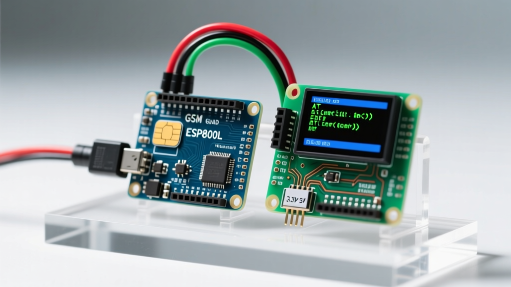

The 2026 Landscape: Navigating GSM Board Arduino Integration
Configuring a GSM board for Arduino projects requires navigating strict power requirements, logic level mismatches, and an evolving cellular landscape. While legacy modules like the SIM800L were the undisputed kings of DIY IoT a decade ago, the global rollout of 4G LTE-M and NB-IoT networks has fundamentally shifted how we approach cellular microcontroller projects today. According to Cisco's IoT networking guidelines, legacy 2G and 3G networks are being aggressively sunsetted worldwide, making 4G LTE modules the mandatory standard for reliable, future-proof deployments in 2026.
⚠️ Critical 2026 Warning: If you are using a SIM800L or SIM900 module, be aware that major carriers in North America, Australia, and parts of Europe have completely shut down 2G towers. If your module fails to register on the network (+CREG: 0,0), the hardware is likely fine, but the network it relies on no longer exists in your region. Upgrade to a SIM7600 or A7670 module immediately.
Hardware Selection Matrix: Choosing the Right Module
Selecting the correct GSM board for your Arduino depends on your regional network availability, power budget, and data requirements. Below is a comparison of the most common modules used in the maker community today.
| Module Model | Network Standard | Logic Voltage | Peak Current | Avg Price (2026) |
|---|---|---|---|---|
| SIM800L (V2) | 2G GSM/GPRS | 3.3V - 4.4V | 2.0A | $6 - $9 |
| SIM7600G-H | 4G LTE (Global) | 3.3V | 2.5A | $35 - $45 |
| SIMCom A7670 | 4G LTE Cat-1 | 3.3V | 2.0A | $18 - $25 |
| Quectel EC25 | 4G LTE Cat-4 | 1.8V / 3.3V | 2.2A | $40 - $55 |
Power Architecture: Solving the 2A Peak Current Problem
The single most common point of failure in GSM board Arduino configurations is inadequate power delivery. When a GSM module transmits data or registers with a distant cell tower, it draws massive current spikes—often up to 2.0A to 2.5A for a few milliseconds. The onboard 5V linear regulator of an Arduino Uno or Mega is typically rated for a maximum of 800mA and will trigger a thermal shutdown or experience severe voltage sag under this load. This results in the module continuously rebooting or dropping the network connection.
The Dedicated Buck Converter Setup
Never power a GSM module directly from the Arduino's 5V or 3.3V pins. Instead, use a dedicated step-down (buck) converter. As detailed in Adafruit's GSM power architecture documentation, proper decoupling is just as critical as the power source itself.
- Power Source: Use a 7V-12V 2A (minimum) wall adapter or a high-discharge LiPo battery (e.g., 2000mAh 3.7V with a boost converter).
- Voltage Regulation: Connect an LM2596 or MP1584 buck converter to the main power rail. Adjust the potentiometer to output exactly 4.0V (ideal for SIM800L) or 5.0V (if using a SIM7600 shield with onboard regulation).
- Decoupling Capacitors: Solder a 100µF electrolytic capacitor and a 0.1µF ceramic capacitor directly across the VBAT and GND pins of the GSM module. This local energy reservoir handles the microsecond transmission spikes that the buck converter cannot react to fast enough.
- Common Ground: Crucially, you must connect the GND of the Arduino, the GND of the buck converter, and the GND of the GSM module together. Without a shared ground reference, serial communication will fail entirely.
Logic Level Translation: Protecting the RX Pin
Most standard Arduinos (Uno, Nano, Mega) operate at 5V logic levels. However, the serial RX/TX pins on almost all modern GSM boards (including the SIM800L and SIM7600) are strictly 3.3V tolerant. Feeding a 5V TX signal from the Arduino into the 3.3V RX pin of the GSM module will degrade the silicon over time and eventually destroy the UART transceiver.
The Solution: Use a bidirectional logic level shifter (such as a BSS138 MOSFET-based module) between the Arduino and the GSM board. If you are in a pinch and need a quick prototype fix, you can build a unidirectional voltage divider for the Arduino TX to Module RX line using a 1kΩ and 2kΩ resistor. Connect the 1kΩ resistor to the Arduino TX, the 2kΩ resistor to GND, and tap the 3.3V signal from the junction to feed into the GSM RX pin. The Module TX to Arduino RX line can usually be connected directly, as the Arduino's ATmega328P reliably recognizes 3.3V as a HIGH signal.
AT Command Configuration Workflow
Once wired correctly, configuration is handled via AT commands over UART. While older tutorials rely on the retired Arduino GSM library, modern 2026 best practices dictate using raw AT commands via HardwareSerial or the AltSoftSerial library for better timing accuracy.
Expert Tip: Avoid using the default SoftwareSerial library at baud rates above 38400. As noted in the official Arduino SoftwareSerial documentation, software-based UART struggles with CPU interrupts at higher speeds, leading to dropped packets and corrupted AT responses. Always default to 9600 or 19200 baud for software serial, or use an Arduino Mega's hardware serial ports (Serial1, Serial2) for 115200 baud LTE data streams.
Essential Initialization Sequence
Send these commands sequentially upon boot, waiting for the OK response after each:
AT: Tests basic UART communication. Expected response:OK.ATE0: Disables command echoing to simplify parsing in your C++ code.AT+CPIN?: Checks SIM card status. Expected:+CPIN: READY. If you get+CME ERROR: 10, your SIM is missing or the socket pins are oxidized.AT+CSQ: Queries signal quality. Response format:+CSQ: [rssi],[ber]. An RSSI of 10-14 is marginal, 15-19 is usable, and 20+ is excellent. An RSSI of 99 means no signal or antenna failure.AT+CREG?: Checks network registration.+CREG: 0,1means registered on the home network.0,5means registered while roaming.AT+CGDCONT=1,"IP","your.apn.here": Defines the Packet Data Protocol (PDP) context for internet access. You must replace the APN with your specific carrier's APN (e.g., "fast.t-mobile.com" or "iot.nb").
Troubleshooting Common Failure Modes
Even with perfect wiring, cellular environments are unpredictable. Here is how to diagnose the most frequent edge cases encountered in the field:
1. Module Reboots During SMS or Data Transmission
Symptom: The module responds to basic AT commands but restarts (losing network registration) the exact moment you send AT+CMGS (Send SMS) or open a TCP socket.
Diagnosis: Voltage sag. The transmission burst exceeds the power supply's transient response capability.
Fix: Increase the capacitance on the VBAT line to 470µF or 1000µF, and ensure the wiring from the buck converter to the module uses thick (18 AWG or lower) silicone wire to minimize resistance.
2. Persistent '+CREG: 0,0' (Network Search Timeout)
Symptom: The module powers on, returns OK to AT commands, but never registers on the network, even after 5 minutes.
Diagnosis: Antenna impedance mismatch, 2G network shutdown, or SIM provisioning issue.
Fix: First, verify the antenna is tuned for the correct frequency (e.g., 900MHz vs 1800MHz). Second, test the SIM card in a standard smartphone to ensure it is active and not locked to a specific IMEI. Finally, verify your module's frequency bands match your local carrier's active LTE bands.
3. Garbage Characters in the Serial Monitor
Symptom: You receive hieroglyphics or random symbols instead of OK.
Diagnosis: Baud rate mismatch or missing common ground.
Fix: Some SIM7600 modules default to 115200 baud out of the factory, while many Arduino sketches default to 9600. Send AT+IPR=9600 at 115200 baud to permanently lock the module to 9600, then update your Arduino Serial.begin() to match.