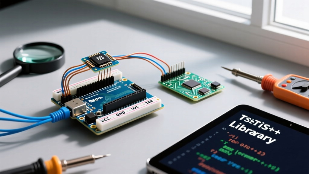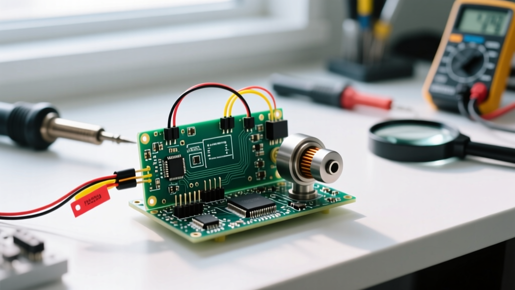

The Evolution of the Arduino Tach in the Maker Community
Building a reliable Arduino tach (tachometer) is a rite of passage for makers working with motors, engines, and rotating machinery. While the basic concept—counting pulses to determine Revolutions Per Minute (RPM)—is straightforward, achieving laboratory-grade accuracy requires navigating hardware limitations, electromagnetic interference (EMI), and microcontroller timing quirks. As of 2026, the maker community has moved far beyond simple delay()-based polling loops. Today, we are leveraging hardware interrupts, timer capture registers, and advanced decoupling techniques to build tachometers that rival commercial units costing hundreds of dollars.
In this community resource roundup, we explore the most robust hardware configurations, the best open-source libraries, and the critical mathematical edge cases you need to master to build a flawless Arduino tachometer.
Hardware Selection: Optical vs. Magnetic Tach Sensors
The foundation of any Arduino tachometer is the sensor. The community generally splits into two camps: optical (infrared) and magnetic (Hall effect). Choosing the right sensor dictates your wiring complexity, maximum measurable RPM, and susceptibility to environmental noise.
| Sensor Model | Type | Max Reliable RPM | Avg. Cost (2026) | Best Use Case |
|---|---|---|---|---|
| TCRT5000 | Optical (IR) | ~10,000 RPM | $1.50 / 5-pack | Indoor, clean environments, low-vibration setups |
| A3144 | Hall Effect | ~25,000 RPM | $2.00 / 10-pack | Dirty environments, enclosed gears, high-EMI zones |
| OMRON D2F-L | Mechanical Microswitch | ~3,000 RPM | $1.20 / unit | Low-speed conveyors, heavy machinery (requires debouncing) |
| Rotary Encoder (600 P/R) | Optical Incremental | ~5,000 RPM | $18.00 / unit | Precision CNC spindles, closed-loop motor control |
Deep Dive: The A3144 Hall Effect Sensor
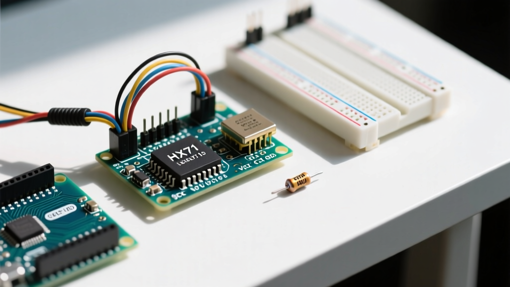
The A3144 remains the undisputed community favorite for rugged Arduino tach projects. It triggers when a magnetic south pole approaches and releases when the field weakens. However, a common failure mode in beginner builds is EMI-induced false triggering. When measuring the RPM of brushed DC motors or ignition systems, the electromagnetic noise can induce voltage spikes in the sensor's signal wire. Community Best Practice: Always solder a 0.1µF ceramic decoupling capacitor directly across the VCC and GND pins of the A3144, as close to the sensor body as physically possible. Additionally, use a 10kΩ pull-up resistor on the signal line to 5V, even if you enable the Arduino's internal pull-ups, to ensure a stiff logic high in noisy environments.
Deep Dive: The TCRT5000 Optical Sensor
Optical sensors are perfect for measuring the RPM of 3D printer cooling fans or PC blowers. The TCRT5000 uses an IR LED and a phototransistor. The primary enemy here is ambient light interference. Sunlight or high-CRI workshop LEDs can saturate the phototransistor, causing the Arduino tach to read zero. Makers solve this by 3D printing shrouds (using opaque PETG or ABS) and applying a strip of reflective tape to the rotating shaft, while painting the rest of the shaft matte black to maximize contrast.
Top Community-Tested Libraries for RPM Measurement
Writing raw interrupt service routines (ISRs) is educational, but for production-grade maker projects, leveraging community-maintained libraries saves hours of debugging.
1. PJRC FreqMeasure Library
For those using Teensy boards or standard Arduino Unos/Nanos, the PJRC FreqMeasure Library is the gold standard. Instead of relying on software interrupts which can be delayed by other code execution, this library utilizes the microcontroller's hardware Timer1 Input Capture pin. This means the exact microsecond of the pulse edge is recorded by the hardware itself, completely immune to software jitter. It is the most accurate method for building an Arduino tach capable of measuring high-speed spindles.
2. EnableInterrupt for Multi-Sensor Arrays
If your project requires monitoring multiple tachometers simultaneously (e.g., a 4-wheel drive robot chassis), the standard Arduino attachInterrupt() function limits you to just two external interrupt pins (Pins 2 and 3 on the Uno/Nano). The EnableInterrupt library allows you to assign pin-change interrupts to almost any digital pin on the ATmega328P, enabling complex multi-tach arrays without upgrading to a Mega or Due.
The Math: Handling micros() Overflow and Jitter
The most common mathematical error in Arduino tachometer code involves the micros() function. The micros() timer overflows and resets to zero approximately every 70 minutes. If your code simply subtracts the previous timestamp from the current timestamp, an overflow will result in a massive negative number, which, when cast to an unsigned long, results in a wildly incorrect RPM spike.
Community Tip: Never useif (currentTime > previousTime)for timing logic. Always use unsigned subtraction:unsigned long elapsed = currentTime - previousTime;. The properties of two's complement binary arithmetic guarantee that the elapsed time will be calculated correctly even if the timer rolls over between the two readings.
The RPM Formula:
To calculate RPM accurately without floating-point drift, use integer math wherever possible:
RPM = (60000000UL * pulseCount) / (elapsedMicros * pulsesPerRevolution);
Note the UL suffix. This forces the compiler to treat 60,000,000 as an Unsigned Long, preventing 16-bit integer overflow during the multiplication step.
Step-by-Step: Wiring an Interrupt-Driven Arduino Tach
- Power the Sensor: Connect the sensor VCC to the Arduino 5V pin and GND to GND. Do not power high-draw sensors from the 3.3V regulator.
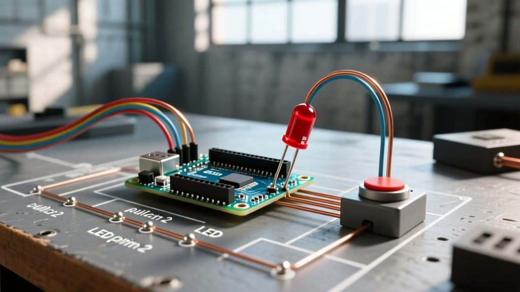
- Signal Routing: Connect the sensor output to Arduino Digital Pin 2 (Hardware Interrupt 0).
- Pull-up Configuration: If using an open-collector Hall sensor, connect a 10kΩ resistor between Pin 2 and 5V.
- ISR Setup: In your
setup(), useattachInterrupt(digitalPinToInterrupt(2), tachISR, FALLING);. UsingFALLINGorRISINGis generally preferred overCHANGEto avoid double-counting noisy signal edges. - Volatile Variables: Declare your pulse counter as
volatile unsigned long pulseCount = 0;so the compiler knows it can be modified asynchronously by the ISR.
Troubleshooting Common Arduino Tach Failure Modes
Even with perfect code, hardware realities can ruin your readings. Here are the most frequent edge cases discussed in maker forums:
- Double Triggering (Contact Bounce): If using a mechanical switch or a noisy Hall sensor, a single magnet pass might register as 3 or 4 pulses. Fix: Implement a software debounce in the ISR by ignoring any interrupts that occur within 500 microseconds of the last valid trigger.
- Stalled Motor Reads: If the motor stops, the time between pulses approaches infinity, causing a divide-by-zero error in your RPM calculation. Fix: Implement a watchdog timer in your main loop. If
micros() - lastPulseTime > 1000000(1 second), force the RPM variable to 0. - Serial Print Bottlenecks: Printing RPM to the Serial Monitor inside the ISR or at every loop iteration will block the microcontroller, causing missed interrupts. Fix: Only calculate and print the RPM every 250ms using a non-blocking
millis()timer.
Community Spotlight: Standout Open-Source Projects
The true power of the Arduino ecosystem lies in shared knowledge. In 2026, several GitHub repositories have set the standard for tachometer implementations. Look for projects that combine Timer1 Input Capture with I2C OLED displays for standalone, PC-free RPM gauges. Additionally, the integration of ESP32 microcontrollers has allowed makers to build WiFi-enabled tachometers that log RPM data to InfluxDB and Grafana dashboards for long-term motor health monitoring. By studying these open-source architectures, you can elevate your Arduino tach from a simple weekend project to a professional-grade diagnostic tool.