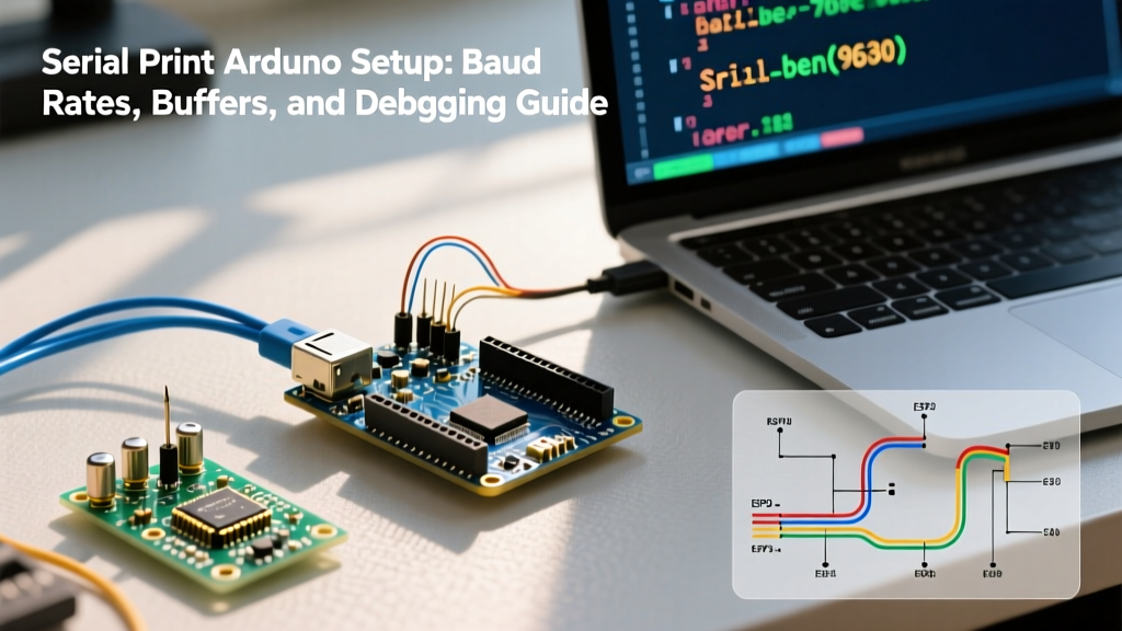

The Hidden Complexities of Serial Print Arduino Communication
For most makers, the Serial.print() function is the very first tool learned and the most frequently abused. While it serves as the backbone of microcontroller debugging, treating serial communication as a simple 'fire-and-forget' command often leads to silent data corruption, blocked execution loops, and SRAM exhaustion. As of 2026, with the proliferation of complex IoT sketches and high-speed sensor arrays on boards like the Arduino Uno R4 Minima and ESP32, properly configuring your serial output is no longer optional.
This configuration guide dives deep into the hardware realities of UART and USB-CDC architectures, baud rate timing errors, transmit buffer overflows, and advanced hardware debugging techniques to ensure your Serial.print Arduino implementation is robust, non-blocking, and memory-efficient.
Hardware Layer: UART vs. USB-CDC Architectures
Before configuring baud rates, you must understand how your specific board handles serial data. The term 'Serial' abstracts away two fundamentally different hardware architectures:
1. Hardware UART with USB-to-Serial Bridge
Classic boards like the Arduino Uno R3 (ATmega328P) utilize a hardware UART peripheral that communicates via physical TX and RX pins (D1 and D0). A secondary microcontroller (usually an ATmega16U2) acts as a bridge, converting the UART signals to USB for your PC. When you call Serial.begin(9600), you are configuring the main MCU's UART hardware, and the data is pushed to the bridge regardless of whether a serial monitor is open on your PC.
2. Native USB-CDC (Communication Device Class)
Modern boards like the Arduino Leonardo (ATmega32U4), Zero (SAMD21), and ESP32-S3 feature native USB peripherals. Here, Serial does not map to physical UART pins by default; it maps to a virtual COM port over USB. Critical Configuration Note: On native USB boards, serial data is not transmitted unless a host application (like the IDE Serial Monitor) is actively connected and asserting the DTR (Data Terminal Ready) signal. If your sketch relies on serial output to trigger external logic without a PC attached, it will silently fail unless you implement connection-checking routines or map your output to Serial1 (hardware UART).
Baud Rate Configuration and Timing Errors
Baud rate defines the bit-rate of your serial line. While the Arduino IDE Serial Monitor defaults to 9600, modern applications demand 115200 or higher to prevent bottlenecking. However, baud rates are not arbitrary; they are derived from the microcontroller's system clock, and mismatched timing results in corrupted data (often appearing as garbage characters like ÿ or ?).
According to the official Arduino Serial Reference, the hardware calculates the UART Baud Rate Register (UBRR) based on the oscillator frequency. On a standard 16MHz ATmega328P, the UART uses a 'Double Speed' (U2X) mode to minimize error.
| Target Baud Rate | 16MHz Crystal Error % | 8MHz Crystal Error % | Reliability Verdict |
|---|---|---|---|
| 9600 | 0.2% | 0.2% | Flawless (Standard Legacy) |
| 57600 | 0.8% | 1.4% | Highly Reliable |
| 115200 | 2.1% | -3.5% | Reliable (Standard Modern) |
| 250000 | 0.0% | 0.0% | Perfect (Hidden Gem) |
| 500000 | 0.0% | 0.0% | Perfect (High Speed) |
| 1000000 | 0.0% | 0.0% | Perfect (Max Hardware) |
Expert Insight: Notice that 250000, 500000, and 1000000 baud yield a 0% timing error on 16MHz crystals, whereas 115200 carries a 2.1% error. While 2.1% is well within the standard ±5% UART tolerance, if you are communicating over long RS-485 lines or noisy environments, configuring your Serial.print Arduino sketch to use 250000 baud will yield mathematically perfect bit timing and reduce packet corruption.
TX Buffer Overflow and Blocking Execution
The most common point of failure in time-critical sketches is the transmit (TX) buffer. On standard AVR-based Arduinos, the hardware serial TX buffer is strictly limited to 64 bytes.
When you execute Serial.print(), the characters are placed into this SRAM buffer, and an interrupt service routine (ISR) shifts them out to the TX pin one by one. If you attempt to print a 200-byte JSON payload at 115200 baud, the first 64 bytes are buffered instantly. The remaining 136 bytes will block the main loop until space frees up. At 115200 baud, each byte takes approximately 0.87 milliseconds to transmit. A 200-byte print statement will halt your entire microcontroller for roughly 175 milliseconds. In a PID motor controller or a high-frequency sensor polling loop, this 175ms blackout will cause catastrophic system instability.
Implementing Non-Blocking Serial Prints
To prevent loop blocking, you must monitor the buffer state before writing. Use the Serial.availableForWrite() function to implement non-blocking serial transmission:
Pro-Tip: Never use
Serial.flush()to 'speed up' your code. In modern Arduino cores,Serial.flush()does exactly the opposite: it blocks execution until the TX buffer is completely empty. Only use it right before putting the MCU to sleep to prevent data truncation.
Memory Optimization: SRAM vs. Flash Storage
When using Serial.print() with string literals, beginners often unknowingly exhaust their microcontroller's volatile memory. Consider this line:
Serial.print("System Initialized Successfully. Awaiting Commands...");
On an ATmega328P with only 2KB of SRAM, the compiler stores this string literal in SRAM by default. If you have dozens of debug statements scattered throughout your sketch, you will trigger an SRAM overflow, leading to erratic behavior, corrupted variables, and spontaneous reboots. The heap and stack will collide, destroying your application state.
The Configuration Fix: Always wrap static serial strings in the F() macro. This forces the compiler to store the string in Flash memory (Program Space), which is abundant (32KB on the Uno), and streams it directly to the serial port byte-by-byte during execution.
Serial.print(F("System Initialized Successfully. Awaiting Commands..."));
For ESP32 and RP2040 boards, which feature hundreds of kilobytes of SRAM, this is less critical but remains a best practice for cache efficiency and code portability.
Advanced Buffer Resizing for ESP32 and SAMD Boards
Unlike the rigid 64-byte AVR buffer, modern 32-bit architectures allow dynamic buffer reallocation. If you are configuring an ESP32 for heavy telemetry logging, you can increase the TX buffer size during the setup() phase before calling Serial.begin().
According to the ESP32 Arduino Core Documentation, you can utilize Serial.setTxBufferSize(1024) to expand the buffer to 1KB. This allows you to dump massive sensor arrays into the serial buffer instantly without blocking the dual-core RTOS tasks running on the ESP32.
Hardware Debugging: When the IDE Monitor Fails
Software configuration is only half the battle. When your Serial.print Arduino output shows nothing in the IDE, or outputs intermittent garbage, the issue often lies in the physical layer. Relying solely on the Arduino IDE Serial Monitor blinds you to hardware-level faults like voltage sag, baud rate drift, or shorted TX lines.
To achieve true E-E-A-T level debugging, integrate a logic analyzer into your toolkit:
- Saleae Logic Pro 8 ($119): The industry standard. Capable of sampling up to 500 MS/s, it perfectly decodes UART packets and visually highlights framing errors or parity mismatches in real-time.
- FX2LP-based Generic Analyzers (~$12): Excellent for budget makers. When paired with the open-source Sigrok/PulseView software ecosystem, these cheap USB dongles can decode 115200 baud UART streams flawlessly up to 24MHz sampling rates.
Diagnostic Workflow: Clip the logic analyzer's Channel 0 to the MCU's TX pin and Ground to the GND pin. Set the protocol decoder to 'UART' and match your configured baud rate. If the logic analyzer decodes the packet perfectly but your PC serial monitor shows garbage, your issue is a USB-CDC driver bug or a faulty USB cable lacking proper shielding. If the logic analyzer shows framing errors, your baud rate math is incorrect, or the MCU's crystal oscillator is drifting due to thermal load.
Summary Checklist for Production Serial Configs
- Verify if your board uses Hardware UART or Native USB-CDC.
- Select a mathematically optimal baud rate (e.g., 250000 for 16MHz AVRs).
- Wrap all static debug strings in the
F()macro to protect SRAM. - Implement
Serial.availableForWrite()checks for payloads exceeding 64 bytes. - Use a hardware logic analyzer to verify physical layer integrity before blaming your code.
By treating Serial.print() as a configurable hardware peripheral rather than a simple print statement, you eliminate the most common hidden bottlenecks in embedded systems design.