
The Core Conflict: TTL vs. RS-232 Voltage Logic
Integrating legacy hardware into modern maker projects remains a critical skill in 2026. While USB-C and Ethernet dominate consumer electronics, the RS-232 standard is stubbornly relevant in industrial automation, CNC machining (like Mach3 controllers), scientific instruments, and legacy PLCs. However, attempting to connect an RS-232 device directly to an Arduino's UART pins is a guaranteed way to destroy your microcontroller.
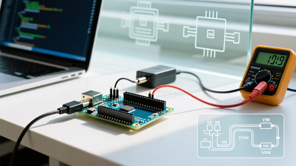
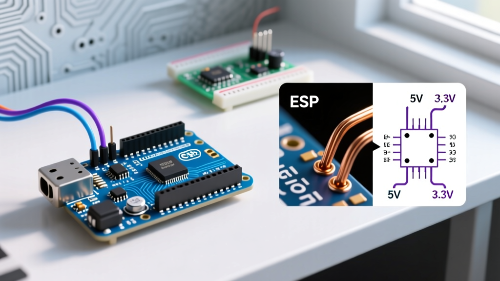
The fundamental incompatibility lies in voltage logic. Arduino boards (whether based on the ATmega328P, ESP32, or SAMD21) utilize Transistor-Transistor Logic (TTL) for serial communication. In contrast, the RS-232 standard, governed by the EIA/TIA-232 specification, uses high-voltage, bipolar signaling designed for noise immunity over long, unshielded cables.
Voltage Logic Matrix
| Logic State | TTL (Arduino 5V) | TTL (Arduino 3.3V) | RS-232 Standard |
|---|---|---|---|
| Logic 1 (Mark) | ~5.0V | ~3.3V | -3V to -15V |
| Logic 0 (Space) | ~0V | ~0V | +3V to +15V |
⚠️ CRITICAL WARNING: Notice that RS-232 Logic 1 is represented by a negative voltage, and Logic 0 by a positive voltage. Feeding a -12V RS-232 "Mark" signal directly into an Arduino's RX pin will instantly forward-bias internal protection diodes, permanently frying the GPIO pin and potentially destroying the entire MCU.
The Hardware Bridge: MAX3232 and Charge Pump Physics
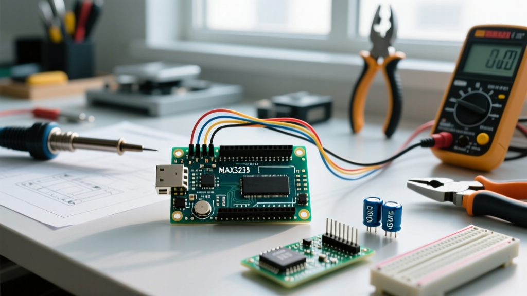
To safely use RS232 with Arduino, you must use a level-shifting transceiver IC. The industry standard is the Texas Instruments MAX3232 (or the older, 5V-only MAX232). As of 2026, pre-assembled MAX3232 breakout boards are widely available from maker retailers for roughly $4.00 to $9.00 USD.
The Charge Pump Capacitor "Gotcha"
The MAX3232 operates from a single 3.3V or 5V supply but must generate +/- 10V to meet RS-232 specifications. It achieves this using an internal charge pump circuit that requires four external fly capacitors. Here is where most DIY tutorials fail, leading to silent data corruption:
- MAX232 (Legacy 5V IC): Requires 1.0µF capacitors.
- MAX3232 (Modern 3.3V/5V IC): Requires 0.1µF capacitors.
If you mistakenly use 1.0µF capacitors on a MAX3232 board, the charge pump oscillator frequency drops drastically. The IC will still output a signal, but the voltage swing might only reach +/- 4V. While this might work on a desk with a 2-foot cable, it will fail the RS-232 receiver threshold in an electrically noisy factory environment or over cables longer than 15 feet.
Step-by-Step Wiring Guide
When wiring your level shifter, you must manage two distinct domains: the TTL side (Arduino) and the RS-232 side (DB9 connector).
- VCC & GND: Connect the breakout board VCC to the Arduino 5V (or 3.3V if using an ESP32). Connect GND to GND. Do not skip the ground connection; RS-232 is single-ended and relies on a shared ground reference.
- TTL Routing: Connect the MAX3232
T1INto the Arduino TX pin. ConnectR1OUTto the Arduino RX pin. - RS-232 Routing: Connect
T1OUTto the DB9 RX pin (Pin 2). ConnectR1INto the DB9 TX pin (Pin 3).
DTE vs. DCE: The Null Modem Edge Case
A frequent point of failure when interfacing RS232 with Arduino is ignoring DTE (Data Terminal Equipment) and DCE (Data Circuit-terminating Equipment) classifications. A standard PC is a DTE device. If you program your Arduino to act as a DTE device (mimicking a PC terminal) and plug it directly into another PC via a standard straight-through DB9 cable, you will connect TX to TX and RX to RX.
The Fix: You must use a Null Modem adapter or cable, which internally crosses the TX and RX lines (Pin 2 to Pin 3). Conversely, if you are connecting the Arduino to a CNC machine or PLC that acts as DCE, a standard straight-through cable is correct. Always verify the target device's pinout manual before soldering your DB9 connector.
Firmware Strategy: SoftwareSerial vs. Hardware Serial
On standard Arduino Uno or Nano boards, hardware UART pins (0 and 1) are shared with the onboard ATmega16U2 USB-to-Serial chip. If you connect an RS-232 transceiver to these pins, the RS-232 device will interfere with your USB connection, preventing you from uploading new sketches or using the Serial Monitor for debugging.
The professional approach is to utilize the Arduino SoftwareSerial library to bit-bang a secondary UART on digital pins 10 and 11. This leaves the hardware serial port free for USB debugging.
#include <SoftwareSerial.h>

// Define RS-232 TTL pins (RX, TX)
SoftwareSerial rs232Serial(10, 11);

void setup() {
  // Hardware serial for USB debugging
  Serial.begin(9600);
  // Software serial for RS-232 device
  rs232Serial.begin(9600);
  Serial.println("RS-232 Bridge Initialized.");
}

void loop() {
  // Pass RS-232 data to USB Monitor
  if (rs232Serial.available()) {
    Serial.write(rs232Serial.read());
  }
  // Pass USB Monitor input to RS-232
  if (Serial.available()) {
    rs232Serial.write(Serial.read());
  }
}
Note: SoftwareSerial is reliable up to 57600 baud, but 9600 or 19200 is highly recommended for stability, as bit-banging at higher speeds can drop bytes during interrupt service routines (ISRs).
Industrial Troubleshooting Matrix
When deploying RS-232 Arduino bridges in real-world environments, use this diagnostic matrix to resolve common anomalies.
| Symptom | Root Cause | Actionable Solution |
|---|---|---|
| Garbage characters in Serial Monitor | Baud rate mismatch or Inverted Logic | Verify target device baud rate (often 19200 for industrial). Some legacy GPS modules use inverted TTL; use the inverted parameter in SoftwareSerial if applicable. |
| Works on desk, fails on factory floor | Ground Loops & EMI | RS-232 is highly susceptible to ground loops. Introduce an opto-isolated RS-232 transceiver (e.g., Analog Devices ADM3251E) or switch the architecture to RS-485 for differential signaling. |
| Arduino resets when plugging in DB9 | Charge Pump Backfeed / Ground Fault | Ensure the DB9 shield is NOT tied to signal ground on the Arduino side. Verify the MAX3232 GND is tied to Arduino GND, not the chassis ground of the target machine. |
| Intermittent dropped bytes at 38400 baud | SoftwareSerial ISR Overload | Reduce baud rate to 9600, or upgrade to an Arduino Mega / ESP32 which features multiple dedicated hardware UARTs, eliminating the need for SoftwareSerial entirely. |
Summary and Best Practices
Successfully using RS232 with Arduino requires respecting the physical layer differences between TTL and bipolar signaling. Always use a dedicated level-shifter IC like the MAX3232, verify your fly capacitor values (0.1µF for MAX3232), and map out your DTE/DCE topology to avoid Null Modem confusion. For deeper insights into serial protocols and physical layer wiring, the SparkFun Serial Basic Hookup Guide remains an excellent foundational resource for makers bridging the gap between modern microcontrollers and legacy hardware.