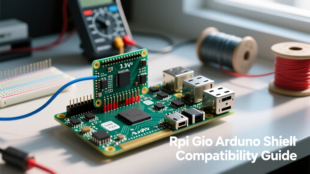

When integrating a Raspberry Pi into a traditional microcontroller ecosystem, the Raspberry Pi RPi GPIO header presents a unique set of compatibility challenges. While the Pi is a powerhouse for high-level computing, computer vision, and network routing, it lacks the native hardware peripherals and 5V tolerance of an ATmega328P or ESP32. Makers frequently attempt to plug Arduino shields directly into the Pi's 40-pin header, often resulting in catastrophic silicon failure or erratic peripheral behavior.
This compatibility guide dissects the electrical and architectural differences between the Raspberry Pi RPi GPIO and standard Arduino headers, providing actionable frameworks for safe voltage translation, pinout mapping, and shield integration.
The 3.3V vs 5V Logic Level Divide
The most critical difference between an Arduino Uno (based on the ATmega328P) and a modern Raspberry Pi (using the BCM2711 or BCM2712 SoC) is the logic level voltage. Arduino boards operate at 5V logic, meaning a HIGH signal is typically 5V. The Raspberry Pi RPi GPIO pins operate strictly at 3.3V.
Critical Warning: Never connect a 5V Arduino digital output directly to a Raspberry Pi GPIO pin. The BCM2711 SoC absolute maximum rating on VDD_IO is 3.6V. Exceeding this threshold will permanently destroy the ARM core's silicon.
Safe Voltage Translation Methods
To safely bridge a 5V Arduino shield to the Raspberry Pi RPi GPIO, you must use a logic level shifter. Not all shifters are created equal, and choosing the wrong IC can lead to bus capacitance issues on high-speed lines like SPI.
- BSS138 MOSFET Boards: Ideal for I2C and low-speed UART. They are bi-directional and cheap, but the parasitic capacitance limits them to roughly 400kHz, making them unsuitable for high-speed SPI displays.
- Texas Instruments TXS0108E: Features auto-direction sensing and edge-rate acceleration. Excellent for SPI and 1-Wire, but can struggle with I2C clock stretching due to its internal pull-up current sources.
- Texas Instruments TXB0108: Better suited for general-purpose push-pull GPIO and UART, but lacks the open-drain compatibility required for I2C.
Pinout Mapping: RPi GPIO to Arduino Headers
Arduino shields expect a specific physical and electrical layout defined by the Uno R3 or Mega 2560 form factors. To use these shields with a Raspberry Pi, you must map the functions, not just the physical pin numbers. Below is a translation matrix for the most critical Arduino Uno pins to their Raspberry Pi RPi GPIO equivalents.
| Arduino Uno Pin | Primary Function | Raspberry Pi RPi GPIO Equivalent | Compatibility Notes |
|---|---|---|---|
| D0 (RX) | Hardware UART RX | GPIO 15 (Pin 10 / UART0_RXD) | Requires disabling Linux serial console via raspi-config. |
| D1 (TX) | Hardware UART TX | GPIO 14 (Pin 8 / UART0_TXD) | 3.3V output; use level shifter if talking to 5V MCU. |
| D2 | External Interrupt 0 | GPIO 17 (Pin 11) | Pi supports software interrupts on all GPIO pins. |
| D3 | PWM / Interrupt 1 | GPIO 18 (Pin 12 / PWM0) | One of the few Pi pins with true hardware PWM. |
| A4 (SDA) | I2C Data | GPIO 2 (Pin 3 / I2C1_SDA) | Pi requires external 2.2k pull-ups to 3.3V. |
| A5 (SCL) | I2C Clock | GPIO 3 (Pin 5 / I2C1_SCL) | Pi I2C bus capacitance limit is ~400pF. |
| D10 (SS) | SPI Slave Select | GPIO 8 (Pin 24 / SPI0_CE0) | Active LOW; maps perfectly to Pi SPI Chip Enable 0. |
| D11 (MOSI) | SPI Master Out | GPIO 10 (Pin 19 / SPI0_MOSI) | Ensure shield uses standard SPI, not bit-banged. |
| D12 (MISO) | SPI Master In | GPIO 9 (Pin 21 / SPI0_MISO) | 3.3V logic; most 5V SPI sensors output 3.3V high. |
| D13 (SCK) | SPI Clock | GPIO 11 (Pin 23 / SPI0_SCLK) | Pi SPI clock can reach 125MHz, but shields max at 8MHz. |
Shield Compatibility Matrix and Failure Modes
Plugging an Arduino shield into a Raspberry Pi breakout board requires analyzing the shield's underlying circuitry. Here is how common shield categories interact with the Raspberry Pi RPi GPIO.
Motor and Relay Shield Failures
Older Arduino motor shields based on the L293D H-bridge IC are notorious for failing when adapted to the Pi. The L293D requires a minimum of 4.5V on its logic input pins to register a HIGH signal. Because the Raspberry Pi RPi GPIO only outputs 3.3V, the motor shield will simply ignore the Pi's commands. Solution: Use modern I2C-based motor controllers like the Adafruit Motor Shield V2, which uses a PCA9685 PWM driver chip that operates perfectly at 3.3V logic.
Similarly, standard 5V relay modules often feature an optocoupler (like the PC817) and a status LED in series. The forward voltage drop of the LED plus the optocoupler's internal diode often exceeds 3.3V, meaning the Pi cannot trigger the relay. You must bypass the status LED or use a relay module with a dedicated MOSFET driver triggered by 3.3V logic.
Sensor and Prototyping Shields
Analog sensor shields are entirely incompatible out-of-the-box. The Raspberry Pi lacks an onboard Analog-to-Digital Converter (ADC). If you are using a shield that relies on Arduino pins A0 through A3 for analog readings (like a joystick shield or analog soil moisture sensor), you must integrate an external ADC via I2C or SPI, such as the Texas Instruments ADS1115 (16-bit) or the Microchip MCP3008 (10-bit SPI).
I2C and SPI Bus Quirks on the Pi
The electrical behavior of the communication buses on the Raspberry Pi differs significantly from the ATmega328P, leading to silent failures if ignored.
I2C Pull-Up Resistor Requirements
According to the official Raspberry Pi documentation, the primary I2C bus (GPIO 2 and GPIO 3) does not feature internal pull-up resistors enabled by default at the hardware level. While some software libraries attempt to enable them, it is unreliable. When connecting 5V Arduino I2C shields, you must disable the shield's onboard 5V pull-ups (often by cutting a trace or removing a jumper) and install physical 2.2kΩ or 4.7kΩ resistors pulling SDA and SCL to the Pi's 3.3V rail.
SPI Clock Stretching and Jitter
Unlike the deterministic hardware SPI of an Arduino, the Raspberry Pi runs a multitasking Linux kernel. If you are bit-banging SPI or relying on software-based chip selects, OS interrupts will cause clock jitter. Always use the dedicated hardware SPI0 pins mapped in the table above, and ensure your Python or C++ code utilizes the SPI hardware abstraction layers rather than manual GPIO toggling to maintain signal integrity.
Hardware PWM vs Software Jitter
Arduino boards utilize dedicated hardware timers to generate flawless PWM signals for servo control and LED dimming. The Raspberry Pi RPi GPIO, by contrast, primarily relies on software-generated PWM via the OS. This results in severe jitter, causing servos to twitch or buzz audibly.
To achieve Arduino-like hardware PWM on the Pi, you are restricted to specific pins. On the BCM2711 (Pi 4), only GPIO 12, 13, 18, and 19 support true hardware PWM. If your shield requires PWM on arbitrary pins, you must use the pigpio library. Pigpio utilizes the Pi's DMA (Direct Memory Access) controller to generate highly accurate, jitter-free software PWM, effectively bridging the gap between Linux and bare-metal MCU timing.
Current Sourcing Limitations
A standard Arduino Uno pin can safely source or sink 20mA, with a total package limit of 200mA. The Raspberry Pi RPi GPIO pins are vastly more fragile. A single Pi GPIO pin should not exceed 3mA to 5mA for continuous safe operation, and the entire 3.3V GPIO bank is limited to roughly 50mA total. Attempting to drive a standard 20mA LED directly from a Pi GPIO pin without a current-limiting resistor will cause severe voltage sag across the 3.3V rail, potentially resetting the Pi or corrupting the SD card. Always use NPN transistors (like the 2N2222) or logic-level MOSFETs to switch high-current loads.