
Introduction to the JD9853 Industrial Power Module
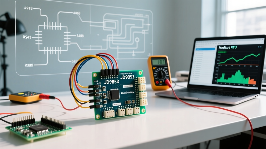
As makers and DIY engineers increasingly build custom smart-home energy dashboards and solar inverter telemetry systems in 2026, the JD9853 single-phase AC energy meter module has emerged as a highly reliable, cost-effective alternative to basic I2C sensors like the INA219. Priced typically between $16 and $24 on global maker marketplaces, the JD9853 provides true RMS voltage, current, active power, and cumulative energy readings via an isolated RS485 interface.
However, interfacing industrial RS485 sensors with 5V or 3.3V microcontroller logic is a frequent stumbling block. This comprehensive JD9853 Arduino compatibility guide covers the exact hardware level-shifting requirements, Modbus RTU register maps, and software configurations needed to successfully integrate this module into your next power-monitoring project without risking your microcontroller.
Core Hardware Compatibility: Logic Levels & RS485 Transceivers
The JD9853 communicates using the Modbus RTU protocol over a differential RS485 bus. Microcontrollers like the Arduino Uno, Mega, or ESP32 do not natively output differential RS485 signals; they output single-ended TTL UART (TX/RX). Therefore, a transceiver module is strictly required.
Choosing the Right Transceiver Module
While the ubiquitous $0.80 MAX485 clone modules found in starter kits will technically work for bench testing, they lack galvanic isolation. In a real-world AC mains monitoring environment, ground loops can easily destroy your Arduino's ATmega328P or ESP32 silicon. For permanent installations, we strongly recommend using an isolated RS485 transceiver based on the ADM2587E or MAX14840A chipsets (costing around $4 to $7), which provide up to 5kV of isolation.
⚠️ CRITICAL VOLTAGE WARNING: The JD9853 RS485 A/B lines operate at 5V differential. If you are using a 3.3V microcontroller like the ESP32 or Arduino Nano 33 IoT, you must use a logic-level shifting transceiver or an isolated module with dedicated 3.3V VCC logic inputs to prevent back-feeding 5V into your MCU's GPIO pins.Wiring Matrix: JD9853 to Arduino Uno & Mega
Proper wiring is the foundation of Modbus reliability. Below is the definitive pinout matrix for connecting the JD9853 to popular Arduino boards via a standard MAX485 or SP3485 breakout board.
| JD9853 Pin | MAX485 Module Pin | Arduino Uno (5V) | Arduino Mega 2560 | ESP32 (3.3V Logic) |
|---|---|---|---|---|
| VCC (5V-12V) | VCC | 5V (or external 5V PSU) | 5V | 3V3 (if isolated module) |
| GND | GND | GND | GND | GND |
| RS485-A+ | A | N/A (Differential) | N/A (Differential) | N/A (Differential) |
| RS485-B- | B | N/A (Differential) | N/A (Differential) | N/A (Differential) |
| N/A | DI (Data In) | D11 (SoftwareSerial RX) | D19 (Serial1 RX) | GPIO 16 (Serial2 RX) |
| N/A | RO (Data Out) | D12 (SoftwareSerial TX) | D18 (Serial1 TX) | GPIO 17 (Serial2 TX) |
| N/A | DE & RE (Jumpered) | D10 (Direction Control) | D8 (Direction Control) | GPIO 4 (Direction Control) |
Note: The DE (Driver Enable) and RE (Receiver Enable) pins on the transceiver must be jumpered together and connected to a single digital output pin on the Arduino to manage the half-duplex transmit/receive switching.
Software Compatibility: Modbus RTU Libraries
The JD9853 defaults to a Modbus slave address of 0x01, a baud rate of 9600, and a frame format of 8-N-1 (8 data bits, No parity, 1 stop bit). To parse the binary Modbus RTU frames and handle the CRC16 checksum calculations automatically, you must use a robust library.
We recommend the ModbusMaster Library by Doc Walker. It is highly optimized for AVR and ESP architectures and handles the precise timing delays required between Modbus frames (the 3.5 character silence period) as defined by the Modbus Organization Technical Specifications.
The SoftwareSerial Bottleneck
If you are using an Arduino Uno, you will likely rely on the SoftwareSerial library since the hardware UART (D0/D1) is reserved for USB programming. Be aware that SoftwareSerial is highly unstable at baud rates above 19200. Fortunately, the JD9853's default 9600 baud rate falls safely within SoftwareSerial's reliable operating window. If you alter the JD9853's baud rate to 115200 via its configuration software, an Arduino Uno will fail to read it; you must upgrade to an Arduino Mega or ESP32 to utilize hardware serial ports.
C++ Implementation: Reading JD9853 Registers
Below is a production-ready C++ snippet for the Arduino Mega (using Hardware Serial1) to read the Voltage, Current, and Active Power registers from the JD9853. The JD9853 typically stores these as 16-bit unsigned integers, where Voltage is scaled by 0.1V and Current by 0.001A.
#include <ModbusMaster.h>

#define MAX485_DE      8
#define MAX485_RE_NEG  8

ModbusMaster node;

void preTransmission() {
  digitalWrite(MAX485_RE_NEG, 1);
  digitalWrite(MAX485_DE, 1);
}

void postTransmission() {
  digitalWrite(MAX485_RE_NEG, 0);
  digitalWrite(MAX485_DE, 0);
}

void setup() {
  pinMode(MAX485_RE_NEG, OUTPUT);
  pinMode(MAX485_DE, OUTPUT);
  digitalWrite(MAX485_RE_NEG, 0);
  digitalWrite(MAX485_DE, 0);

  Serial.begin(115200); // Debug console
  Serial1.begin(9600);  // JD9853 RS485 Bus

  node.begin(1, Serial1); // Slave ID 1
  node.preTransmission(preTransmission);
  node.postTransmission(postTransmission);
}

void loop() {
  uint8_t result = node.readHoldingRegisters(0x0000, 3);

  if (result == node.ku8MBSuccess) {
    float voltage = node.getResponseBuffer(0x00) * 0.1;   // Register 0x00
    float current = node.getResponseBuffer(0x01) * 0.001; // Register 0x01
    float power   = node.getResponseBuffer(0x02) * 0.1;   // Register 0x02

    Serial.print("V: "); Serial.print(voltage);
    Serial.print(" | A: "); Serial.print(current);
    Serial.print(" | W: "); Serial.println(power);
  } else {
    Serial.print("Modbus Error Code: 0x");
    Serial.println(result, HEX);
  }
  delay(1000);
}
Common Failure Modes & Troubleshooting Edge Cases
Even with correct wiring, RS485 networks are susceptible to environmental noise. If your JD9853 is returning Modbus Error 0xE0 (Timeout) or 0xE1 (Invalid CRC), investigate the following hardware-specific failure modes:
- Missing Termination Resistors: RS485 buses require a 120Ω termination resistor across the A+ and B- lines at both physical ends of the cable. While the JD9853 often has a jumper for this, cheap MAX485 modules do not. If your cable run exceeds 2 meters, solder a 120Ω resistor directly across the A/B screw terminals to prevent signal reflection.
- Bus Biasing (Floating Lines): When the Arduino is in Receive mode (DE/RE LOW), the RS485 bus is high-impedance and floating. Electromagnetic interference from nearby AC mains cables can induce phantom voltages, causing UART framing errors. Install a 560Ω pull-up resistor from A+ to VCC (5V) and a 560Ω pull-down resistor from B- to GND to bias the idle state to a logical '1'.
- Ground Reference Mismatch: Although RS485 is differential, the transceiver chips still require a common ground reference to keep the common-mode voltage within the -7V to +12V operating range. Always run a dedicated GND wire alongside your A+ and B- twisted pair, especially if the JD9853 and Arduino are powered by separate switched-mode power supplies.
- Modbus Slave Address Conflicts: Out of the box, almost all JD9853 modules ship with Slave ID
0x01. If you daisy-chain multiple JD9853 modules on the same RS485 bus to monitor different breaker phases, you must use a USB-to-RS485 dongle and a PC-based Modbus polling tool to change the slave IDs to0x02,0x03, etc., before connecting them to the Arduino.
Summary
Integrating the JD9853 with an Arduino provides a robust, industrial-grade solution for AC power telemetry. By respecting the 5V/3.3V logic boundaries, utilizing proper RS485 biasing and termination networks, and leveraging hardware Serial ports where possible, you can eliminate the packet loss and CRC errors that plague amateur Modbus implementations. Whether you are building a DIY smart breaker panel or an off-grid solar monitor, the JD9853 paired with an Arduino Mega or ESP32 offers unparalleled accuracy for under $30 in total component costs.