
Quick Reference: Arduino Encoder Specifications
Selecting the right rotary encoder is critical for precision motor control, user interfaces, and robotics. Below is a quick-reference matrix comparing the most common encoders used in the maker and prosumer space as of 2026.
| Model | Type | PPR (Pulses/Rev) | Operating Voltage | Approx. Cost (2026) |
|---|---|---|---|---|
| KY-040 Module | Mechanical | 20 PPR | 3.3V - 5V | $1.50 - $3.00 |
| LPD3806-600BM-G5-24C | Optical | 600 PPR | 5V - 24V | $14.00 - $18.00 |
| CUI Devices AMT103 | Capacitive | 2048 PPR | 5V (Open-Collector) | $22.00 - $28.00 |
| US Digital S5 | Optical | 50 - 1000 PPR | 5V | $35.00 - $45.00 |
Frequently Asked Questions (FAQ)
1. How do I wire a standard 5-pin KY-040 encoder to an Arduino?
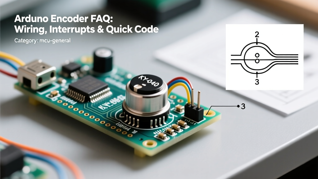
The KY-040 is the most ubiquitous entry-level encoder. It features 5 pins: CLK (Clock), DT (Data), SW (Switch/Button), + (VCC), and GND. For optimal performance on a 5V Arduino Uno or Mega, wire it as follows:
- VCC: Connect to 5V (or 3.3V if using an ESP32 or Arduino Nano 33 IoT).
- GND: Connect to system ground.
- CLK: Connect to a hardware interrupt pin (Pin 2 on Uno/Nano).
- DT: Connect to a secondary digital pin (Pin 3 on Uno/Nano).
- SW: Connect to any standard digital pin (e.g., Pin 4). Use
INPUT_PULLUPin your code.
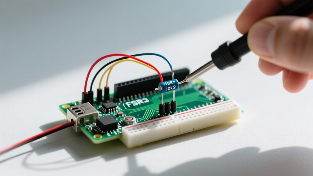
Expert Tip: Many cheap KY-040 breakout boards lack onboard pull-up resistors for the CLK and DT lines. If your readings are erratic, solder two 10kΩ resistors between VCC and the CLK/DT pins to stabilize the high state.
2. What is the difference between PPR and CPR?
This is the most common trap for beginners. PPR (Pulses Per Revolution) refers to the number of complete square wave cycles on a single channel per 360-degree rotation. However, because quadrature encoders output two channels (A and B) offset by 90 degrees, you can detect four distinct state changes (edges) per cycle. Therefore, CPR (Counts Per Revolution) is exactly 4 times the PPR. A 600 PPR optical encoder yields 2400 CPR, providing an angular resolution of 0.15 degrees per count.
3. How does Quadrature Gray Code decoding actually work?
Quadrature encoders output two square waves (Channel A and Channel B) that are 90 degrees out of phase. By reading the state of both channels simultaneously, you can determine both position and direction. The state transitions follow a Gray Code sequence, meaning only one bit changes at a time, preventing massive counting errors during transitions.
| Previous State (A,B) | Current State (A,B) | Direction |
|---|---|---|
| 00 | 10 | Clockwise (CW) |
| 10 | 11 | Clockwise (CW) |
| 11 | 01 | Clockwise (CW) |
| 01 | 00 | Clockwise (CW) |
| 00 | 01 | Counter-Clockwise (CCW) |
| 01 | 11 | Counter-Clockwise (CCW) |
| 11 | 10 | Counter-Clockwise (CCW) |
| 10 | 00 | Counter-Clockwise (CCW) |
4. Should I use hardware interrupts or timer-based polling?
For low-resolution mechanical encoders (like the 20 PPR KY-040) used for user menus, timer-based polling at 1kHz to 5kHz is often superior. It inherently bypasses contact bounce and saves hardware interrupts for more critical tasks. However, for high-resolution optical encoders (600+ PPR) attached to fast-spinning motors, hardware interrupts are mandatory. Using the PJRC Encoder Library is highly recommended, as it utilizes optimized interrupt service routines (ISRs) that handle the Gray Code state machine in C++ without blocking the main loop.
5. Why is my encoder skipping steps or registering double clicks?
This is almost always caused by contact bounce in mechanical encoders. When the internal metal wipers make or break contact, they physically vibrate, creating micro-second voltage spikes that the Arduino interprets as dozens of rapid rotations. You must implement debouncing.
6. What is the best hardware debouncing circuit for an Arduino encoder?
While software debouncing (ignoring state changes within a 5ms window) works for slow UI knobs, it fails at high RPMs. The industry-standard hardware fix is an RC (Resistor-Capacitor) low-pass filter combined with a Schmitt trigger inverter (like the 74HC14). For a quick DIY fix without the IC, solder a 470nF (0.47µF) ceramic capacitor between the CLK pin and GND, and another between the DT pin and GND. Paired with a 10kΩ pull-up resistor, this creates a time constant ($\tau = R \times C$) of 4.7ms, effectively smoothing out the mechanical bounce while preserving edge integrity for standard knob-turning speeds.
Troubleshooting Matrix: Common Encoder Failures
Use this diagnostic matrix to quickly resolve edge cases encountered in the lab or field.
| Symptom | Probable Cause | Actionable Fix |
|---|---|---|
| Count goes backward when turning clockwise. | Swapped Phase A and Phase B signals. | Swap the wires connected to the CLK and DT pins, or invert the logic in software. |
| Random massive spikes in position data. | EMI (Electromagnetic Interference) from nearby stepper motors or VFDs. | Switch to shielded twisted-pair (STP) cable. Use differential line drivers (RS-422) for runs over 2 meters. |
| Code compiles on Uno but fails on Arduino R4 Minima. | Direct port manipulation (e.g., reading PIND) in legacy ISR code. | The R4 Minima uses a Renesas ARM Cortex-M4. Replace AVR register calls with digitalReadFast() or standard digitalRead() inside the ISR. |
| Encoder works via USB but fails on battery power. | Voltage sag dropping below the encoder's logic threshold. | Ensure the encoder VCC is tied to a regulated 5V rail, not raw battery input. Add a 100µF bulk decoupling capacitor at the encoder's VCC/GND pins. |
Modern Microcontroller Considerations (2026 Update)
As the maker ecosystem has shifted toward 32-bit architectures, handling encoder interrupts has evolved. The legacy Arduino Uno (ATmega328P) only supports hardware interrupts on Pins 2 and 3. If you are building a multi-axis CNC or a complex robot requiring 3+ encoders, the Uno is fundamentally bottlenecked.
Upgrading to an ESP32-S3 or the Arduino R4 Minima solves this. The ESP32-S3 allows you to attach hardware interrupts to almost any of its GPIO pins via the attachInterrupt() function. Furthermore, the ESP32 features a dedicated Pulse Counter (PCNT) peripheral built into the silicon. By configuring the PCNT via the ESP-IDF or advanced Arduino core libraries, the hardware decodes the quadrature signals entirely in the background without triggering a single CPU interrupt, freeing your main loop to run WiFi stacks or complex kinematics at maximum speed.
Authoritative Resources for Further Reading
- Arduino Official Documentation: attachInterrupt() - The definitive guide to mapping ISR vectors across different Arduino architectures.
- PJRC Encoder Library Documentation - Essential reading for understanding optimized quadrature decoding and cross-platform compatibility.
- CUI Devices Rotary Encoder Catalog - Excellent reference for selecting industrial-grade capacitive and optical encoders when mechanical modules fail.