
Understanding the VIN Pin Arduino Power Architecture
The VIN (Voltage Input) pin on an Arduino Uno R3, Nano, or Mega 2560 is one of the most frequently misunderstood interfaces in the maker community. Unlike the 5V pin, which feeds directly into the microcontroller's power rail, or the USB port, which passes through a dedicated polyfuse and auto-switching circuit, the VIN pin routes external power directly into the board's onboard linear voltage regulator. When projects fail, reset unexpectedly, or refuse to boot, the root cause often traces back to how power is being delivered through this specific pin.
As of 2026, while newer microcontroller ecosystems have largely transitioned to switching regulators, the classic ATmega328P-based boards still rely on legacy linear regulation. Diagnosing VIN-related errors requires a firm grasp of dropout voltages, thermal dissipation limits, and reverse-polarity protection circuits. This guide provides a deep-dive diagnostic framework for identifying and resolving VIN pin failures.
The Anatomy of the Arduino VIN Circuit
To troubleshoot effectively, you must understand the physical path electrons take from the VIN pin to the ATmega328P VCC pin. According to the official Arduino Uno Rev3 documentation, the power section comprises three critical stages:
- The Protection Diode (M7): A surface-mount rectifier diode placed in series with the VIN pin. It prevents catastrophic damage if a user accidentally reverses the polarity of a battery pack connected to the barrel jack or VIN/GND headers.
- The Linear Regulator (NCP1117ST50T3G): A 5V, 1A linear regulator housed in an SOT-223 package. It steps down the VIN voltage to a stable 5V logic level.
- The Auto-Switching Comparator: On the Uno R3, an LMV358 op-amp comparator monitors the VIN voltage. If VIN exceeds roughly 6.6V, it drives a P-channel MOSFET (typically an FDN340P) to disconnect the USB 5V rail, preventing backpowering conflicts.
Diagnostic Matrix: Symptoms vs. Root Causes
When a board fails to power up or behaves erratically, use this diagnostic matrix to correlate your multimeter readings with the underlying hardware failure.
| Symptom | Voltage at VIN | Voltage at 5V Pin | Probable Root Cause |
|---|---|---|---|
| Board resets when servos move | 9.0V (Stable) | Drops to 4.1V | Regulator Thermal Shutdown |
| Dead board, no LEDs, no serial | 0.0V | 0.0V | Blown Polyfuse (RX30) or Shorted M7 Diode |
| Brownouts with 5V USB power bank | 4.9V | 3.8V | Dropout Voltage Failure |
| Board gets too hot to touch | 12.0V | 5.0V | Excessive Power Dissipation (Linear Inefficiency) |
Error 1: Thermal Shutdown and the Overheating Regulator
The most common VIN pin error is thermal shutdown. The NCP1117 is a linear regulator, meaning it burns off excess voltage as heat. As detailed in the ON Semiconductor NCP1117 Datasheet, the SOT-223 package has a junction-to-ambient thermal resistance ($\theta_{JA}$) of approximately 50°C/W to 80°C/W, depending on the PCB copper pour.
The Thermal Math
Power dissipation ($P_d$) is calculated as: P_d = (V_in - V_out) * I_load.
Suppose you power your Uno via VIN with a 12V wall adapter and connect an ESP8266 Wi-Fi module and two micro-servos drawing a combined 300mA (0.3A).
- Voltage Drop: 12V - 5V = 7V
- Power Dissipated: 7V * 0.3A = 2.1 Watts
- Temperature Rise: 2.1W * 60°C/W = 126°C rise above ambient.
If your room is 25°C, the regulator junction hits 151°C. The NCP1117 features internal thermal shutdown circuitry that triggers at roughly 160°C. In this scenario, the regulator will rapidly overheat, shut down, cool off, and restart—causing your Arduino to endlessly boot-loop whenever the servos or Wi-Fi radio draw peak current.
Expert Fix: Never draw more than 150mA from the 5V pin when using a 9V or 12V input on VIN. For high-current peripherals, bypass the onboard regulator entirely and use an external buck converter.
Error 2: Dropout Voltage and the 5V USB Bank Fail
A frequent mistake in portable projects is attempting to power the VIN pin using a standard 5V USB power bank via a custom cable. This results in a dropout voltage error. According to SparkFun's Voltage Regulator Tutorial, linear regulators require a minimum input-to-output voltage differential to maintain regulation, known as the dropout voltage.
The NCP1117 has a typical dropout voltage of 1.1V at maximum load. Therefore, to get a stable 5.0V out, you must supply at least 6.1V into the VIN pin. If you feed 5.0V into VIN, the regulator cannot step it up; it simply passes it through minus the internal voltage drop. Your ATmega328P will receive roughly 3.8V to 4.0V. While the chip might run at 8MHz with this voltage, the standard 16MHz crystal oscillator will fail to stabilize, leading to corrupted serial data, failed uploads, and random memory faults.
Error 3: The Missing Polyfuse on Nano Clones
When diagnosing a dead board where VIN measures 0V despite a good battery, the culprit is often a tripped or blown polyfuse. The genuine Arduino Uno R3 features an RX30 500mA resettable PTC polyfuse on the USB line, but the VIN/barrel jack path relies on the M7 diode and the regulator's internal limits.
However, if you are using an Arduino Nano clone (which dominates the 2026 market due to supply chain shifts), the board layout often omits the protection diode to save $0.04 per unit. If a user accidentally swaps the VIN and GND wires on a Nano clone, there is no M7 diode to block the reverse current. The result is an instant, catastrophic short that vaporizes the PCB traces connecting the VIN header to the regulator. Always verify continuity between the VIN header pin and the input leg of the SOT-223 regulator when diagnosing a dead Nano.
Step-by-Step Multimeter Diagnosis Flow
Follow this exact sequence with a digital multimeter (DMM) to isolate VIN pin faults without risking further damage to your microcontroller.
- Isolate the Board: Disconnect all USB cables, shields, and external peripherals. Leave only the power source connected to VIN and GND.
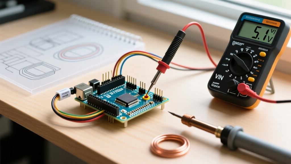
- Verify Source Voltage: Set DMM to DC Voltage. Place the black probe on the GND pin and the red probe on the power source's positive terminal. Ensure it reads between 7V and 12V.
- Measure VIN Header: Move the red probe to the VIN pin on the female header. If the voltage drops significantly from your source measurement, you have a high-resistance connection or a failing battery.
- Measure the 5V Pin: Move the red probe to the 5V output pin.
- If it reads 4.8V to 5.1V, the regulator is healthy.
- If it reads 0V, the NCP1117 is dead, or the M7 diode is open.
- If it reads ~1.5V to 3V, the regulator is in thermal shutdown or the board has a short on the 5V rail pulling the voltage down.
- Short Circuit Test: Power down completely. Set DMM to Continuity/Resistance. Measure between the 5V pin and GND. A reading below 10 ohms indicates a shorted capacitor or a fried ATmega328P, which is dragging the regulator output to ground.
The 2026 Maker's Solution: Switching to Buck Converters
Given the inherent inefficiencies of the NCP1117 linear regulator, modern electrical engineering best practices dictate avoiding the VIN pin for high-draw projects altogether. The recommended approach in 2026 is to use an external switching buck converter.
Modules based on the MP1584EN or LM2596 chips cost between $1.50 and $3.00 on major component marketplaces. Unlike linear regulators that burn excess voltage as heat, switching converters use inductors to step down voltage with >90% efficiency.
How to Bypass the VIN Pin Safely
- Wire your 9V or 12V battery pack directly into the input terminals of the MP1584EN buck converter.
- Use a small flathead screwdriver to turn the potentiometer on the buck converter while monitoring the output terminals with a multimeter until it reads exactly 5.00V.
- Connect the buck converter's 5V output directly to the 5V pin on the Arduino header, not the VIN pin.
- Connect the grounds together.
Warning: When feeding 5V directly into the 5V pin, you are bypassing the Arduino's onboard protection circuitry. Ensure your buck converter is thoroughly tested and stable before connecting it to the microcontroller. Never connect a USB cable simultaneously when backpowering the 5V pin, as this can backfeed voltage into your computer's USB port and damage your motherboard.
Summary
The VIN pin is a convenient but highly constrained power entry point. By understanding the thermal limits of the NCP1117 regulator, respecting the 1.1V dropout threshold, and recognizing the hardware differences between genuine boards and clones, you can accurately diagnose power failures. For any project drawing more than 150mA, abandon the VIN pin in favor of an external switching buck converter to ensure rock-solid reliability and eliminate thermal throttling.