
The Physics of Infrared Communication
When you press a button on a standard remote, you are triggering a rapid sequence of invisible light pulses. An Arduino IR remote control setup relies on near-infrared light, typically peaking at a wavelength of 940 nanometers (nm). This specific wavelength is chosen because it sits just outside the visible spectrum, yet remains highly efficient for standard gallium arsenide (GaAs) photodiodes to detect.
However, ambient light—especially direct sunlight—contains massive amounts of infrared noise. To prevent the receiver from being blinded, the IR LED on the remote does not just turn on and off; it flashes at a specific carrier frequency, almost universally 38 kHz. The receiver contains an internal bandpass filter tuned precisely to 38 kHz, allowing it to ignore steady IR sources like the sun or incandescent bulbs, and only react to the rapidly pulsing signal.
Expert Insight: While 38 kHz is the industry standard for consumer electronics, some specialized HVAC and automotive systems use 36 kHz, 40 kHz, or even 56 kHz carriers. Always verify your target device's carrier frequency using an oscilloscope or a raw IR dump sketch before designing a custom transmitter circuit.
Hardware Anatomy: Transmitters and Receivers
Building a reliable Arduino IR remote control system requires understanding the limitations and specifications of the physical components. In 2026, the market is flooded with cheap clones, making component selection critical for project stability.
The Receiver: TSOP38238 vs. VS1838B
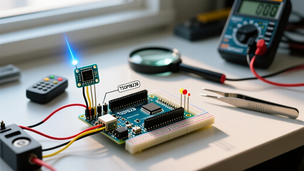
- Vishay TSOP38238 ($0.80 - $1.50): The gold standard for DIY and prototyping. It features an integrated automatic gain control (AGC) circuit, a PIN photodiode, and a preamplifier in a single epoxy package. It handles continuous data streams and offers excellent shielding against electromagnetic interference (EMI).
- Generic VS1838B ($0.05 - $0.15 in bulk): The ubiquitous black cylinder found in cheap Arduino starter kits. While adequate for basic classroom demos, it lacks robust AGC and internal EMI shielding. It frequently suffers from 'phantom triggers' when placed near switching power supplies or cheap LED light drivers.
The Transmitter
A standard 5mm 940nm IR LED can handle a continuous forward current of about 20mA. However, because we are pulsing it at a 38 kHz carrier with a low duty cycle (typically 25%), we can safely drive it with peak currents up to 100mA to 200mA using a simple NPN transistor (like a 2N2222) or a MOSFET. This drastically increases the transmission range from 2 meters to over 10 meters.
Decoding the Signal: Protocol Deep Dive
The 38 kHz carrier is just the physical transport layer. The actual data (which button was pressed) is encoded using specific timing protocols. The SB Projects NEC Protocol Guide remains the definitive industry reference for understanding these timing diagrams.
The NEC Protocol (32-Bit)
The NEC protocol is the most common format for generic 24-key LED strip remotes and standard TV remotes. It uses pulse distance encoding. A standard NEC message consists of:
- AGC Burst: A 9ms mark (carrier on) followed by a 4.5ms space (carrier off) to wake up the receiver's AGC.
- Address & Command: 32 bits of data (8-bit address, 8-bit inverted address, 8-bit command, 8-bit inverted command). The inversion provides built-in error checking.
- Logic 0: 562.5µs mark followed by a 562.5µs space.
- Logic 1: 562.5µs mark followed by a 1.6875ms space.
Protocol Comparison Matrix
| Protocol | Carrier Freq | Encoding Method | Data Length | Typical Use Case |
|---|---|---|---|---|
| NEC | 38 kHz | Pulse Distance | 32 Bits | TVs, LED strips, generic DIY remotes |
| RC-5 (Philips) | 36 kHz | Manchester (Bi-phase) | 14 Bits | Legacy European audio/video equipment |
| Sony SIRC | 40 kHz | Pulse Width | 12, 15, or 20 Bits | Sony Bravia, PlayStation, cameras |
| Samsung | 38 kHz | Pulse Distance | 32 Bits | Modern Samsung TVs and soundbars |
Step-by-Step: Wiring and Decoding with IRremote v4.x
The Arduino-IRremote GitHub Repository is the undisputed standard library for handling these signals. As of version 4.x, the library underwent a massive architectural overhaul to support more MCU architectures and optimize memory. The old IRrecv object syntax is deprecated.
Hardware Wiring
- VCC: Connect to the Arduino 5V pin (or 3.3V if using an ESP32/RP2040 and a 3.3V-tolerant receiver).
- GND: Connect to Arduino GND.
- OUT (Data): Connect to a digital input pin (e.g., Pin 2). Crucial: Add a 100nF ceramic bypass capacitor directly across the VCC and GND pins of the TSOP38238 to filter out high-frequency noise from the Arduino's voltage regulator.
Modern v4.x Implementation Logic
In the modern library paradigm, you initialize the receiver using the global IrReceiver object. You must define the receive pin and specify whether to enable LED feedback (which blinks the onboard LED when a signal is received). The decoding happens in the background via hardware timers, ensuring that a 67ms NEC frame is captured perfectly even if your main loop() is busy running non-blocking delays or updating displays.
Real-World Edge Cases and Interference Mitigation
Theory rarely survives contact with the real world. When deploying an Arduino IR remote control system in a living room or workshop, you will encounter environmental noise. Below is a troubleshooting matrix for common failure modes.
| Symptom | Root Cause | Engineering Solution |
|---|---|---|
| Random phantom button presses when room lights turn on. | Cheap LED bulb drivers emitting broadband EMI in the 30-50 kHz range, overwhelming the receiver's AGC. | Switch to a Vishay TSOP38238 with superior internal shielding. Add a physical IR-pass optical filter (dark red acrylic) over the sensor dome. |
| Signal drops out at distances greater than 3 meters. | Transmitter current starvation.The Arduino GPIO pin can only source ~20mA, which is insufficient for long-range IR. | Drive the IR LED using a logic-level N-channel MOSFET (e.g., 2N7000) and a 10Ω current-limiting resistor to push 150mA peak pulses. |
| Decoding works in serial monitor, but fails when relays trigger. | Relay coil back-EMF causing brownouts on the 5V rail, resetting the MCU or corrupting the timer interrupt. | Use flyback diodes (1N4007) across all relay coils. Power relays from a separate 5V buck converter, sharing only the GND with the Arduino. |
Why IR Still Matters in the Smart Home Era
With the proliferation of Matter, Thread, and BLE Mesh in 2026, you might wonder why infrared remains relevant. The answer lies in line-of-sight security, legacy integration, and BOM (Bill of Materials) cost. An IR transmitter circuit costs less than $0.20 in volume, requires no MAC address provisioning, no Wi-Fi passwords, and cannot be hacked from outside the room. For DIY HVAC zoning, localized lighting control, and interacting with the millions of 'dumb' appliances still in circulation, mastering the Arduino IR remote control concept remains a vital skill for any embedded systems engineer.
Frequently Asked Questions
Can I use an Arduino to control a TV without the original remote?
Yes, but you must first 'sniff' the exact hex codes the TV expects. Using the ReceiveDump example sketch from the IRremote library, point a universal remote (configured to your TV brand) at your TSOP receiver. Record the NEC or Sony SIRC hex values, then program your Arduino to transmit those exact codes using a 940nm IR LED.
Why does my IR receiver output a constant stream of zeros?
This usually indicates that the receiver is saturated by a massive ambient IR source, such as direct sunlight hitting the photodiode, or it is being blasted by high-frequency noise from a nearby switching power supply. Shield the sensor with a small piece of heat-shrink tubing to narrow its field of view and block off-axis light.
Is it possible to send and receive IR simultaneously on one Arduino?
Yes, the IRremote v4.x library supports simultaneous sending and receiving by utilizing separate hardware timers for the PWM carrier generation (TX) and the input capture interrupt (RX). However, you must ensure your TX and RX pins are mapped to the correct timer-associated pins for your specific microcontroller architecture.