
Bridging the Physical and Digital: Understanding Arduino ADCs
Microcontrollers operate in a binary world of ones and zeros, but the physical environment is continuous. To measure real-world phenomena like temperature, light intensity, or pressure, we rely on the Analog-to-Digital Converter (ADC) built into the microcontroller. When working with analog pins on Arduino boards, understanding the underlying hardware limits, proper signal conditioning, and software calibration is the difference between a noisy, unreliable prototype and a production-ready sensor node.
In 2026, the Arduino ecosystem has expanded significantly. While the classic ATmega328P-based boards remain popular for legacy projects, newer architectures like the Renesas RA4M1 (Uno R4) and ESP32-S3 (Nano ESP32) have fundamentally changed how we approach analog readings. This tutorial will guide you through wiring, reading, and calibrating analog sensors, with specific hardware and software techniques to eliminate noise.
Hardware Limits: Comparing Arduino ADC Architectures
Before writing a single line of code, you must know your board's ADC resolution and reference voltage limits. Feeding 5V into an ESP32 analog pin will instantly destroy the microcontroller. Below is a comparison of the most common boards used in maker spaces today.
| Board Model | Microcontroller | ADC Resolution | Max Analog Value | Default VREF | Avg. Price (2026) |
|---|---|---|---|---|---|
| Arduino Uno R3 | ATmega328P | 10-bit | 1023 | 5.0V (VCC) | $27.50 |
| Arduino Uno R4 Minima | Renesas RA4M1 | 14-bit | 16383 | 5.0V / 1.45V | $20.00 |
| Arduino Nano ESP32 | ESP32-S3 | 12-bit | 4095 | 3.3V | $24.00 |
Expert Insight: The ESP32-S3 ADC is notoriously non-linear at the voltage extremes. If you are using a Nano ESP32, design your voltage dividers so the sensor output stays strictly between 0.15V and 3.1V to avoid the flattened 'dead zones' near 0V and 3.3V.
Step-by-Step Wiring: The Voltage Divider Rule
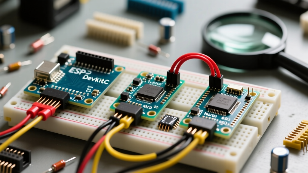
Most resistive sensors—such as NTC thermistors, Light Dependent Resistors (LDRs), and Flex Sensors—do not output a voltage directly. Instead, their resistance changes. To read this change on an analog pin, you must build a voltage divider circuit.
Wiring a 10kΩ NTC Thermistor
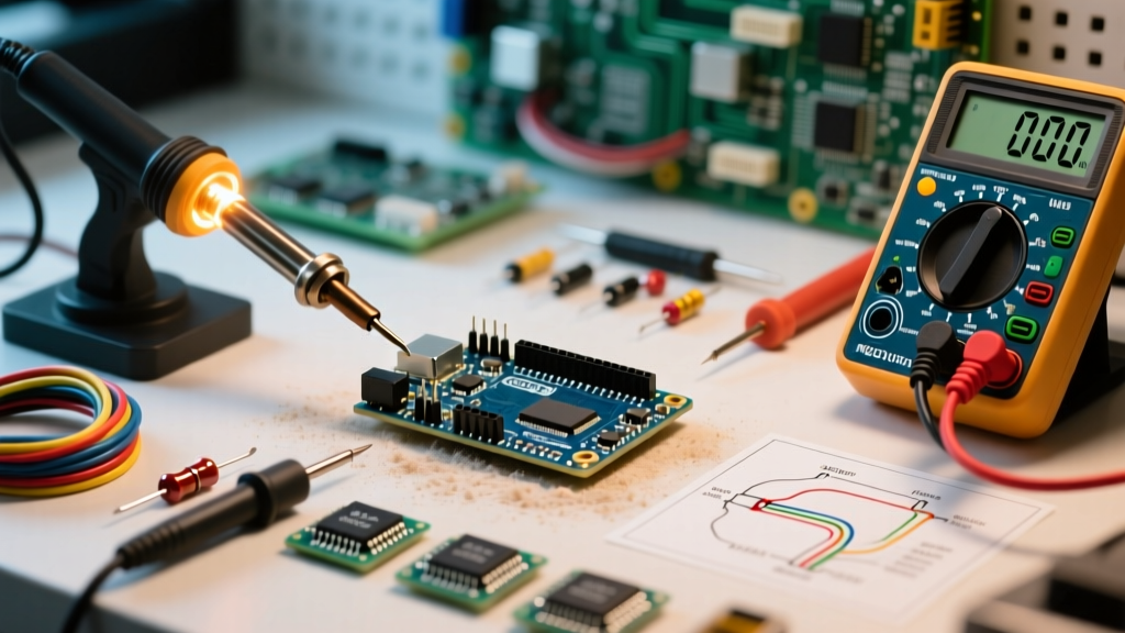
- Connect the Reference Resistor: Solder a precision 10kΩ (1% tolerance) pull-up resistor between the 5V (or 3.3V) pin and Analog Pin A0.
- Connect the Sensor: Connect one leg of the NTC thermistor to A0, and the other leg to GND.
- Condition the Signal: Solder a 100nF (0.1µF) C0G/NP0 ceramic capacitor directly between A0 and GND. This creates a hardware low-pass filter, dramatically reducing high-frequency electromagnetic interference (EMI) before it reaches the ADC sampling capacitor.
As the temperature rises, the NTC's resistance drops, pulling the voltage at A0 closer to GND. The Arduino's ADC measures this voltage drop.
Writing the Sketch: Raw Reads and Voltage Conversion
The core function for reading analog pins is analogRead(). However, simply printing the raw value is rarely useful. You must convert the raw ADC integer back into a physical voltage, and then into your target metric (e.g., Celsius). According to the Arduino Official Language Reference, analogRead() takes roughly 100 microseconds on an ATmega328P, allowing a maximum theoretical read rate of about 9,600 times per second.
// Analog Pin Calibration & Oversampling Sketch for Uno R3
const int sensorPin = A0;
const float vRef = 5.0; // Measure your actual 5V rail with a multimeter!
const int resolution = 1024; // 10-bit for ATmega328P

void setup() {
  Serial.begin(115200);
  // Optional: Use internal 1.1V reference for high-precision low-voltage sensors
  // analogReference(INTERNAL);
}

float readSensorVoltage() {
  long sum = 0;
  // Oversampling: Read 16 times and average to reduce random thermal noise
  for (int i = 0; i < 16; i++) {
    sum += analogRead(sensorPin);
    delayMicroseconds(200); // Allow ADC sampling capacitor to recharge
  }
  float averageADC = sum / 16.0;

  // Convert raw ADC value to actual voltage
  float voltage = (averageADC * vRef) / resolution;
  return voltage;
}

void loop() {
  float vOut = readSensorVoltage();
  Serial.print("Sensor Voltage: ");
  Serial.println(vOut, 4); // Print to 4 decimal places
  delay(500);
}
The VREF Calibration Trap
Notice the vRef = 5.0 variable in the code above. A common beginner mistake is assuming the 5V pin outputs exactly 5.000V. When powered via USB, voltage drops across the Schottky diode and polyfuse often result in a VCC of 4.7V to 4.8V. If your math assumes 5.0V, your sensor readings will be skewed by up to 6%. Always measure the voltage between the 5V and GND pins with a digital multimeter and hardcode that exact value into your sketch.
Advanced Calibration: Defeating Analog Noise
If your serial monitor shows the analog values jumping erratically (e.g., 512, 518, 505, 514), you are experiencing ADC noise. This is caused by switching regulators, digital clock traces, or floating grounds. Tackle this using a two-pronged approach.
1. Hardware Decoupling
Never run long, unshielded wires from a sensor to an analog pin; they act as antennas for 50/60Hz mains hum. Keep analog traces short. If the sensor must be remote, use a shielded twisted-pair cable with the shield tied to GND at the microcontroller end only to prevent ground loops.
2. Software Exponential Smoothing
While oversampling (averaging multiple reads) works well, it consumes memory and slows down the loop. For continuous monitoring, an Exponential Moving Average (EMA) filter is highly efficient. It requires only one floating-point variable and smooths out spikes instantly.
float smoothedValue = 0;
const float alpha = 0.1; // Smoothing factor (0.01 to 0.5)

void loop() {
  float rawRead = analogRead(A0);
  // EMA Formula: New = (Alpha * Raw) + ((1 - Alpha) * Old)
  smoothedValue = (alpha * rawRead) + ((1.0 - alpha) * smoothedValue);

  Serial.println(smoothedValue);
  delay(50);
}
Edge Cases and Troubleshooting Floating Pins
When deploying analog sensors in the field, you will inevitably encounter edge cases that break your logic. Keep this troubleshooting matrix handy:
- Symptom: Random values between 300 and 800 when nothing is connected.
Cause: A floating analog pin acts as a high-impedance antenna, picking up ambient static. Fix: Enable the internal pull-up resistor viapinMode(A0, INPUT_PULLUP)if the pin is temporarily unused, or tie it to GND with a 10kΩ resistor. - Symptom: Value is stuck at 1023 (or 4095 on ESP32).
Cause: The input voltage exceeds the VREF. The ADC is clipping. Fix: Check your voltage divider ratios. Ensure the maximum sensor output never exceeds the board's logic level (5V for Uno, 3.3V for Nano ESP32). - Symptom: Readings drift slowly over hours.
Cause: Thermal drift in the voltage divider resistors or the MCU's internal voltage regulator heating up. Fix: Use metal-film resistors with a low temperature coefficient (e.g., 25ppm/°C) instead of cheap carbon-film resistors for your reference leg. - Symptom: ATmega328P Internal Reference (1.1V) yields incorrect math.
Cause: The internal 1.1V bandgap reference is not exactly 1.1V; it can vary from 1.0V to 1.2V per chip. Fix: If usinganalogReference(INTERNAL), measure the AREF pin with a multimeter and update your sketch's VREF variable to the exact measured millivolt value.
Summary
Mastering the analog pins on Arduino requires looking past the basic analogRead() function. By respecting the hardware limits of your specific microcontroller, implementing proper voltage divider conditioning with C0G capacitors, and applying software oversampling, you can extract lab-grade precision from inexpensive maker hardware. Whether you are logging greenhouse temperatures with an Uno R3 or building a high-speed telemetry node with an R4 Minima, rigorous analog calibration is the foundation of reliable embedded systems.