
The RP1 Southbridge: Why Legacy GPIO Code Fails
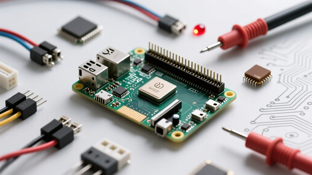
The most common 'error' makers encounter when migrating to the Raspberry Pi 5 is not a hardware failure, but a fundamental architectural shift. Unlike the BCM283x and BCM2711 chips in previous models, the raspberry pi 5 gpio pins are no longer controlled directly by the main application processor (the BCM2712). Instead, they are routed through a dedicated southbridge chip: the Raspberry Pi RP1.
The RP1 is connected to the BCM2712 via a PCIe Gen 2.0 interface. When you attempt to run legacy Python scripts using the deprecated RPi.GPIO library, you will inevitably hit a RuntimeError: Not running on a RPi! or a memory-mapping segmentation fault. This happens because RPi.GPIO attempts to directly access the physical memory addresses of the BCM SoC's GPIO registers, which no longer exist on the Pi 5.
The Software Fix: Migrating to libgpiod
To resolve software-level GPIO errors, you must abandon direct memory access libraries and transition to the Linux standard libgpiod (GPIO character device API). For Python developers, the rpi-lgpio GitHub Repository provides a drop-in shim that mimics the old RPi.GPIO syntax while routing commands safely through the kernel's GPIO character device driver.
pip install rpi-lgpioOnce installed, your existing scripts will interface with the RP1 southbridge correctly, eliminating permission and memory-mapping errors.
Hardware Fault Isolation: Multimeter Diode Testing on RP1
If your software is correctly configured but specific raspberry pi 5 gpio pins refuse to toggle or read high, you may have suffered a hardware fault. The RP1 operates strictly on 3.3V logic. While the RP1 datasheet notes that select GPIO pins possess a degree of 5V tolerance via internal clamping diodes, injecting 5V signals from legacy Arduino modules or unregulated sensors will frequently overwhelm these diodes, permanently shorting the pin to the 3.3V rail or frying the RP1 pad.
The ESD Diode Diagnostic Test
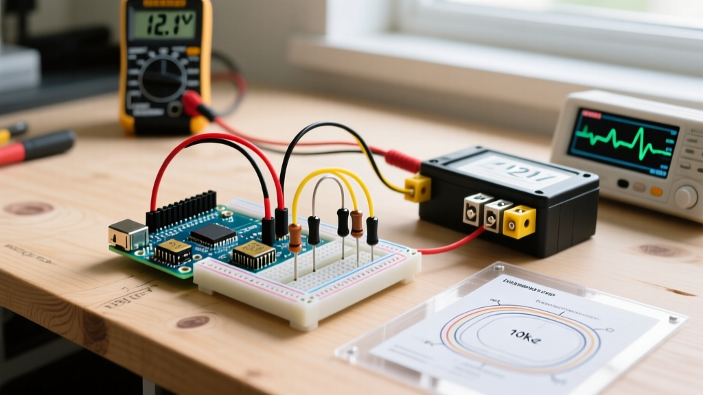
Before replacing your entire Raspberry Pi 5, you can isolate a dead GPIO pin using a standard digital multimeter set to Diode Test Mode.
- Power down the Pi 5 completely and disconnect the USB-C PD cable.
- Set your multimeter to Diode Test (usually indicated by a diode symbol).
- Place the Black (Common) probe on Pin 1 (3.3V Power) or Pin 6 (Ground), depending on the clamping circuit you are testing.
- Place the Red probe on the suspected dead GPIO pin.
Interpreting the Results:
- 0.3V to 0.7V: The internal ESD protection diode is healthy. The hardware is likely fine; suspect a software muxing or pull-up configuration error.
- 0.00V (or continuity beep): The clamping diode has failed short. The pin is permanently tied to the power rail and the RP1 silicon for that pad is destroyed.
- OL (Over Limit / Open): The internal bond wire or diode has blown open. The pin will float unpredictably and cannot be recovered.
Bus Lockups: I2C Clock Stretching and Pull-Up Deficits
Interfacing I2C sensors (like the BME280 or MPU6050) via the raspberry pi 5 gpio pins (specifically GPIO 2 and GPIO 3 for I2C Bus 1) often results in bus lockups, ghost reads, or Remote I/O error messages in Linux. This is rarely a defect in the Pi 5, but rather a mismatch in bus capacitance and clock stretching handling.
The Pull-Up Resistor Deficit
The RP1 chip features internal, software-configurable pull-up resistors. However, these are exceptionally weak (typically around 50kΩ). For a 400kHz Fast-Mode I2C bus, the RC time constant formed by a 50kΩ resistor and the parasitic capacitance of your jumper wires will violate the I2C specification's 300ns maximum rise-time requirement. The RP1 will misinterpret the sluggish voltage ramp as a logic error, dropping the bus.
Expert Rule: Never rely on the RP1 internal pull-ups for I2C. Always populate your I2C HAT or breadboard with external 4.7kΩ (for 100kHz) or 2.2kΩ (for 400kHz) pull-up resistors tied to the 3.3V rail.
Clock Stretching Bugs
Some legacy microcontrollers acting as I2C slaves utilize 'clock stretching' to pause the master while they process data. Early firmware revisions of the RP1 exhibited edge-case timing bugs where it would fail to release the SCL line after a slave stretch event, locking the bus permanently until a reboot. Ensure your Pi 5's EEPROM and kernel are fully updated via sudo apt update && sudo apt full-upgrade to pull the latest RP1 firmware patches from the Raspberry Pi Official GPIO Documentation tree.
Power Delivery Brownouts Masking as Peripheral Disconnects
A highly misunderstood error on the Pi 5 involves peripherals connected to the 5V GPIO pins (Pin 2 and Pin 4) suddenly vanishing or resetting under load. Makers often blame the GPIO header or the RP1 chip, but the root cause is the Power Management IC (PMIC) and USB-C Power Delivery (PD) negotiation.
The Raspberry Pi 5 requires a 5V/5A (27W) PD-capable power supply to unlock full peripheral current limits. If you use a standard 5V/3A charger, the Pi 5's firmware detects the limitation and aggressively throttles the current budget allocated to the USB ports and the 5V GPIO rail. If you connect a relay module or a small OLED display that draws a sudden spike of 500mA, the PMIC's Over-Current Protection (OCP) will trip, instantly dropping the 5V GPIO rail to protect the mainboard. The peripheral dies, and the Linux kernel logs a disconnect, which looks exactly like a GPIO software fault.
Diagnostic Matrix: Symptom to Root Cause Mapping
Use this matrix to rapidly triage your raspberry pi 5 gpio pins errors without guessing.
| Symptom Observed | Probable Root Cause | Diagnostic Action & Fix |
|---|---|---|
RuntimeError: Not running on a RPi |
Using deprecated BCM memory-mapped library. | Uninstall RPi.GPIO; install rpi-lgpio or use gpiozero. |
| Pin reads constant HIGH, won't pull LOW | Blown internal ESD clamping diode (Short to 3.3V). | Perform multimeter diode test. Move to alternate GPIO pin. |
I2C Remote I/O error or bus timeout |
Missing external pull-ups or RP1 clock-stretch bug. | Add 4.7kΩ physical pull-ups; update Pi 5 bootloader firmware. |
| 5V Peripherals randomly resetting | PMIC OCP trip due to 3A adapter current limit. | Upgrade to official 27W USB-C PD power supply. |
| SPI returning garbage data | Logic level mismatch (5V sensor to 3.3V RP1). | Insert a bidirectional logic level shifter (e.g., TXS0108E). |
Expert Verdict: Level Shifting is Non-Negotiable
The transition to the RP1 southbridge makes the Raspberry Pi 5 a vastly more capable machine, but it is entirely unforgiving of 5V logic injection. Unlike older AVRs or certain 5V-tolerant STM32 pins, the RP1 requires strict 3.3V signaling. If your error diagnosis points to erratic reads on multiple pins after connecting a 5V Arduino-style sensor array, you have likely degraded the RP1's input buffers. Invest in dedicated I2C/SPI level shifters and optoisolators for inductive loads (like relays) to ensure your Pi 5 survives the prototyping phase.