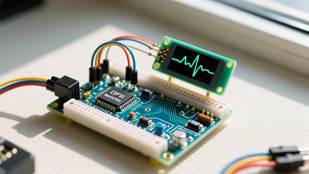

The Evolution of Pulse Detection in the Arduino Community
Building a reliable pulse detector Arduino project has evolved significantly over the last decade. In the early maker days, detecting a pulse—whether a human heartbeat or the RPM of a DC motor—relied on noisy analog circuits and brute-force polling loops. Today, in 2026, the community leverages advanced I2C optical sensors, edge-AI noise filtering, and highly optimized interrupt-driven libraries to achieve medical-grade biometric tracking and industrial-grade mechanical tachometry. This community resource roundup curates the most trusted hardware, software libraries, and troubleshooting frameworks shared across the Arduino Forum, Hackaday, and GitHub repositories.
Community Insight: When designing a pulse detector Arduino circuit, always define your domain early. Biometric optical sensors (like the MAX30102) require high sampling rates and motion artifact rejection, while mechanical pulse detectors (like Hall effect sensors) demand hardware debouncing and precise pull-up resistor configurations.Top Community-Approved Pulse Detector Sensors (2026 Comparison)
The maker community generally divides pulse detection into two categories: biometric (heart rate, SpO2, photoplethysmogram) and mechanical (RPM, flow meters, rotary encoders). Below is a comparison matrix of the most widely deployed sensors in the Arduino ecosystem.
| Sensor Module | Detection Type | Interface | 2026 Avg Price | Best Use Case |
|---|---|---|---|---|
| PulseSensor Amped | Optical (Analog) | 10-bit ADC | $24.95 | Education, basic BPM projects |
| MAX30102 (Generic) | Optical (I2C) | I2C (Fast Mode) | $3.50 - $6.00 | Wearables, SpO2 & HR tracking |
| SparkFun MAX30105 | Optical/Proximity | I2C / INT Pin | $29.95 | Advanced particle sensing, HRV |
| TCRT5000 Reflective | Infrared Optical | Analog / Digital | $1.50 | Water flow meters, line followers |
| A3144 Hall Effect | Magnetic | Digital (Open Collector) | $0.80 | Motor RPM, bicycle speedometers |
Biometric Pulse Detection: Heart Rate & SpO2
The Classic: PulseSensor Amped (Analog)
The green PulseSensor Amped remains a staple in university labs and introductory maker kits. It uses a simple green LED and an ambient light sensor paired with an onboard op-amp circuit to output an analog waveform representing blood volume changes (photoplethysmography or PPG).
Community Best Practice: The most common failure mode reported on the Arduino Forum is 50Hz/60Hz mains hum interference. Because the sensor relies on the Arduino's internal ADC, USB power noise from a PC can completely obscure the dicrotic notch of the pulse wave. Expert makers bypass this by powering the sensor from a clean, battery-sourced 3.3V LDO and using the analogReference(EXTERNAL) function in the sketch to stabilize the ADC baseline.
For software, the community universally recommends the PulseSensor Playground Library. It handles the complex moving-average filters and peak-detection algorithms required to calculate Beats Per Minute (BPM) without blocking the main loop().
The Modern Standard: MAX30102 & MAX30105 Breakouts
For projects requiring clinical accuracy, Heart Rate Variability (HRV) analysis, or blood oxygen saturation (SpO2), the Maxim Integrated (now Analog Devices) MAX30102 is the undisputed community champion. Generic Chinese breakouts cost under $6, while premium versions like the SparkFun MAX30105 (which adds a third LED for particle sensing) retail around $30.
Critical Edge Case - FIFO Overflow: The MAX30102 features an internal 32-sample FIFO buffer. A common mistake in beginner code is polling the sensor via I2C while simultaneously updating an OLED display or sending Serial data. If the main loop stalls for more than a few milliseconds, the FIFO overflows, resulting in skipped heartbeats and wildly inaccurate BPM readings.
"Never poll the MAX30102 in your main loop. Wire the sensor's INT pin to an external hardware interrupt on your Arduino (e.g., Pin 2 on an Uno, or any GPIO on an ESP32). Read the FIFO buffer only when the interrupt fires, ensuring zero data loss even at the maximum 3200 SPS sampling rate." — Embedded Systems Best Practices, Hackaday Community Thread
To implement this, utilize the SparkFun MAX3010x Sensor Library, which includes optimized interrupt-driven examples specifically designed to prevent I2C clock-stretching crashes common on ESP32 and RP2040 microcontrollers.
Mechanical & Industrial Pulse Detection
Not all pulse detectors are meant for human skin. In robotics and home automation, detecting mechanical pulses (like a spinning motor shaft or a ticking water meter) requires entirely different hardware.
TCRT5000 Reflective Optical Sensor
The TCRT5000 pairs an IR emitter with a phototransistor. It is heavily used in DIY water flow meters (detecting the rotation of a reflective impeller) and tachometers. Most community-sourced breakout boards include an LM393 comparator chip with a small blue trimpot.
- Calibration: You must adjust the trimpot with a small Phillips screwdriver while the sensor is in its final physical housing. Ambient sunlight contains massive amounts of IR noise that can blind the phototransistor; adjusting the comparator threshold ensures the digital output pin only triggers on the specific reflective tape applied to your rotating target.
- Wiring: The digital output (DO) pin on the LM393 is open-collector. You must enable the Arduino's internal pull-up resistor (
pinMode(pin, INPUT_PULLUP)) or use an external 10kΩ pull-up resistor to VCC, otherwise, the pin will float and generate phantom pulses.
A3144 Hall Effect Sensor
For environments where dust, oil, or light interference would blind an optical sensor, the A3144 Hall Effect switch is the community's go-to magnetic pulse detector. By taping a small neodymium magnet to a rotating shaft, the A3144 outputs a clean digital LOW pulse every revolution. Like the TCRT5000, it requires a pull-up resistor. For high-RPM applications (above 5,000 RPM), makers are migrating to linear Hall sensors like the DRV5055 paired with a hardware Schmitt trigger to eliminate contact bounce.
Troubleshooting Common Pulse Detector Arduino Failures
Based on thousands of troubleshooting threads from the past year, here is a rapid-response matrix for the most frequent pulse detector Arduino failures:
| Symptom | Probable Cause | Community-Verified Fix |
|---|---|---|
| BPM reads exactly 0 or 255 | I2C Address Conflict or missing pull-ups | Run I2C Scanner sketch. Add 4.7kΩ pull-ups to SDA/SCL if using generic MAX30102. |
| Analog waveform is flatlined at 1023 | Sensor saturation (too much light/current) | Lower LED drive current in MAX3010x registers, or add physical light shielding. |
| Phantom RPM pulses when motor stops | EMI from motor brushes inducing voltage spikes | Add a 0.1µF ceramic capacitor across the sensor's VCC and GND pins. |
Frequently Asked Questions (FAQ)
Can I use an ESP32 instead of an Arduino Uno for pulse detection?
Yes, but with a major caveat. The ESP32's ADC is notoriously non-linear and noisy compared to the ATmega328P found on the Uno R3. If you are using an analog PulseSensor with an ESP32, you must implement software oversampling (reading the pin 64 times and averaging) or use an external I2C ADC like the ADS1115 to maintain waveform fidelity.
How do I calculate Heart Rate Variability (HRV) with these sensors?
HRV requires measuring the exact time delta between successive systolic peaks (the RMSSD metric). You cannot use standard polling delays. You must log the micros() timestamp precisely when the hardware interrupt fires on the MAX30102's INT pin, then pass that array of timestamps to an edge-computing library like TensorFlow Lite Micro to filter ectopic beats before calculating the variance.
What is the maximum cable length for an I2C pulse sensor?
Standard I2C is limited to about 30 centimeters (1 foot) due to bus capacitance. If your pulse detector Arduino project requires the sensor to be mounted on a remote wearable band, you must use an I2C bus extender chip like the P82B715, or switch to a UART-based sensor module to run cables up to several meters without data corruption.