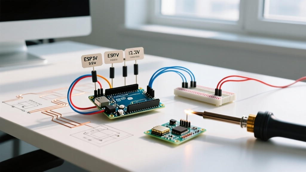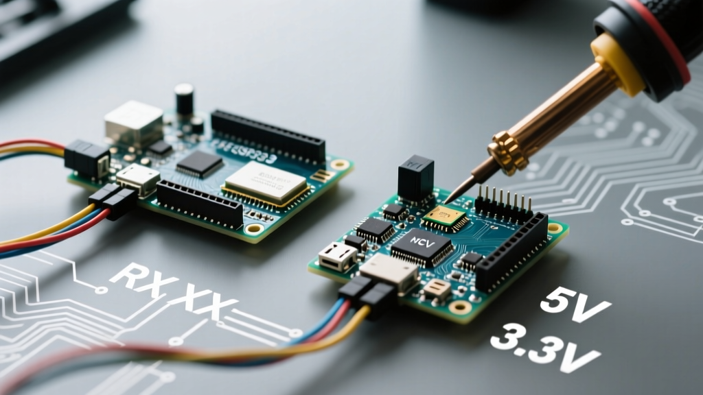

The Hidden Hazards of Arduino to Arduino Serial Communication
Connecting two microcontrollers via UART seems like the most straightforward task in embedded systems. However, as the maker ecosystem has evolved, establishing a reliable Arduino to Arduino serial link has become a compatibility minefield. With the transition from legacy 5V ATmega boards to modern 3.3V ARM and RISC-V architectures (like the Arduino Uno R4, Nano 33 IoT, and ESP32 families), mismatched logic levels, baud rate clock drift, and hardware serial limitations routinely destroy boards or cause silent data corruption.
This compatibility guide dissects the electrical and protocol-level realities of board-to-board serial communication in 2026, providing exact wiring topologies, clock-drift mathematics, and hardware selection frameworks to ensure your data arrives intact.
Board Compatibility Matrix: Voltage and UART Limits
Before wiring a single jumper, you must verify the operating voltage and hardware UART availability of your specific boards. Relying on SoftwareSerial for high-speed inter-board communication is a primary cause of dropped packets.
| Board Model (2026 Standard) | Microcontroller | Logic Level | 5V Tolerant RX? | Hardware UARTs |
|---|---|---|---|---|
| Arduino Uno R3 | ATmega328P | 5.0V | No (Max 5.5V) | 1 |
| Arduino Uno R4 Minima | Renesas RA4M1 | 5.0V | Yes (up to 5.5V) | 2 (1 routed to USB) |
| Arduino Nano 33 IoT | SAMD21 | 3.3V | No (Max 3.6V) | 1 (SERCOM) |
| Arduino Mega 2560 | ATmega2560 | 5.0V | No | 4 |
| ESP32-WROOM-32 | Xtensa LX6 | 3.3V | No (Max 3.6V) | 3 (U0, U1, U2) |
Critical Warning: Feeding a 5V TX line directly into the RX pin of an ESP32 or SAMD21 board will forward-bias the internal ESD protection diodes. While the board might appear to function initially, this causes continuous leakage current, thermal degradation, and eventual silicon failure within weeks of operation.
Logic Level Translation: Bridging the 5V and 3.3V Divide
When establishing an Arduino to Arduino serial link between a 5V master (e.g., Mega 2560) and a 3.3V slave (e.g., ESP32), you must step down the voltage on the TX-to-RX line. The RX-to-TX line (3.3V into a 5V board) is generally safe, as 3.3V exceeds the ATmega328P's V_IH (Input High Voltage) threshold of 0.6 * VCC (which is 3.0V at 5V VCC).
Recommended Level Shifting Hardware
Avoid resistor voltage dividers for baud rates above 19200. The parasitic capacitance of the breadboard and the RX pin (typically 10-15pF) combined with high-value resistors creates a low-pass RC filter, rounding off the square wave and causing framing errors.
- BSS138 MOSFET Bi-Directional Shifter: The industry standard for hobbyists. Costing roughly $1.20 to $1.80 for a 4-channel module in 2026, it uses N-channel MOSFETs to safely translate I2C and UART lines up to 50MHz. Perfect for standard serial speeds.
- TI TXB0108 / TXS0108E: Dedicated auto-direction-sensing ICs. These cost around $2.50 per chip and handle higher edge rates, but can struggle with the open-drain nature of some I2C setups. For pure UART, they are exceptionally reliable.
- Optocouplers (e.g., 6N137): If your Arduino to Arduino serial connection spans more than 3 meters or crosses different power domains (like a motor controller board and a logic board), use high-speed optocouplers to break ground loops and prevent noise injection.
Step-by-Step Wiring: Uno R3 (5V) to ESP32 (3.3V)
- Common Ground: Connect the GND pin of the Uno to the GND pin of the ESP32. Without a shared ground reference, the voltage differential is meaningless, and you will read garbage data.
- Power the Shifter: Connect Uno 5V to the shifter's
HVpin. Connect ESP32 3.3V out to the shifter'sLVpin. Connect shared GND to both shifter GND pins. - Cross the Data Lines: UART requires crossed lines. Connect Uno TX (Pin 1) to Shifter HV1. Connect Shifter LV1 to ESP32 RX (e.g., GPIO 16).
- Return Path: Connect ESP32 TX (e.g., GPIO 17) to Shifter LV2. Connect Shifter HV2 to Uno RX (Pin 0).
The Mathematics of Baud Rate Clock Drift
A frequent, deeply frustrating edge case in Arduino to Arduino serial communication is intermittent data corruption at 115200 baud. This is rarely a software bug; it is a hardware clock limitation.
UART relies on the microcontroller's internal oscillator to sample the incoming signal. The baud rate is generated by dividing the system clock. On a classic 16 MHz Arduino Uno, the formula for the UART Baud Rate Register (UBRR) is:
UBRR = (F_CPU / (16 * Baud)) - 1
If you request 115200 baud on a 16 MHz crystal:
UBRR = (16,000,000 / (16 * 115200)) - 1 = 8.68 - 1 = 7.68
Since the UBRR must be an integer, the compiler rounds to 8.
Let's calculate the actual baud rate achieved:
Actual Baud = 16,000,000 / (16 * (8 + 1)) = 111,111 baud
This results in a -3.55% error. While UART can typically tolerate a ±2% mismatch between sender and receiver, a 3.55% drift on one side, combined with a slight drift on the receiver's crystal, pushes the total timing error beyond the sampling window. By the 10th bit (the stop bit), the receiver samples the line while it is still transitioning, triggering a Framing Error.
The Solution: Baud Rate Sweet Spots
If you are using 16 MHz ATmega boards, avoid 115200 baud for long data streams. Instead, use baud rates that divide cleanly into 16 MHz. According to Arduino's official serial documentation and Microchip datasheets, the following rates yield near-zero error on 16 MHz crystals:
- 76800 baud (0.16% error)
- 57600 baud (0.00% error - Highly Recommended)
- 38400 baud (0.16% error)
Hardware Serial vs. SoftwareSerial Constraints
When your primary hardware UART (Pins 0 and 1) is occupied by the USB-to-Serial chip for PC debugging, developers often default to the SoftwareSerial library. This is a critical compatibility bottleneck.
SoftwareSerial relies on software interrupt timing to bit-bang the UART protocol. It disables interrupts while receiving a byte, meaning no other interrupt-driven processes (like PWM, encoder reading, or I2C) can execute simultaneously. Furthermore, as noted in SparkFun's logic level and serial timing guides, software timing jitter becomes unmanageable above 38400 baud, leading to massive packet loss.
Modern Alternatives to SoftwareSerial
In 2026, you should rarely need SoftwareSerial. Modern boards offer hardware multiplexing:
- ESP32 GPIO Matrix: The ESP32 features three hardware UARTs. Using the
HardwareSerialclass, you can map UART1 or UART2 to almost any available digital GPIO pin via the internal routing matrix, completely eliminating the need for software bit-banging. - SAMD21 / RP2040 SERCOM/PIO: Boards like the Nano 33 IoT or Raspberry Pi Pico allow you to configure multiple SERCOM (Serial Communication) or PIO (Programmable I/O) blocks to act as independent, hardware-buffered UART ports.
- Arduino Mega 2560: Simply use
Serial1(Pins 18/19),Serial2(Pins 16/17), orSerial3(Pins 14/15).
Troubleshooting Checklist for Silent Failures
If your serial monitors are blank or outputting gibberish characters (like ÿ or ?), run through this hardware-level diagnostic matrix:
| Symptom | Probable Cause | Hardware Fix |
|---|---|---|
| Random gibberish characters | Baud rate mismatch or clock drift | Drop both boards to 57600 baud; verify crystal frequencies. |
| Receiver gets nothing | TX/RX lines not crossed | Swap TX and RX wires. TX must always connect to RX. |
| Intermittent dropped bytes | Missing common ground | Run a dedicated GND wire between both MCU ground planes. |
| ESP32 resets randomly | 5V backfeed on RX pin | Insert a BSS138 level shifter on the 5V TX to 3.3V RX line. |
| Works on desk, fails in enclosure | EMI / Capacitive coupling | Use twisted pair cabling for TX/RX; add 220Ω series resistors. |
Final Thoughts on Protocol Selection
While UART is fantastic for point-to-point, asynchronous debugging and simple telemetry, it lacks built-in error checking (beyond a single parity bit) and multi-drop addressing. If your project requires connecting three or more Arduinos together, abandon UART entirely. Transition to an I2C multi-master bus or a differential RS-485 network using MAX485 transceivers (which cost under $0.50 each). For comprehensive hardware translation design, reference the Texas Instruments Logic Level Translator overview to select the exact IC required for your specific voltage domains and edge-rate requirements.
By respecting logic level thresholds, calculating true baud rate errors, and leveraging hardware UART multiplexing, your Arduino to Arduino serial links will remain robust, stable, and immune to the silent failures that plague beginner projects.