
The Physics of Untethered Microcontrollers
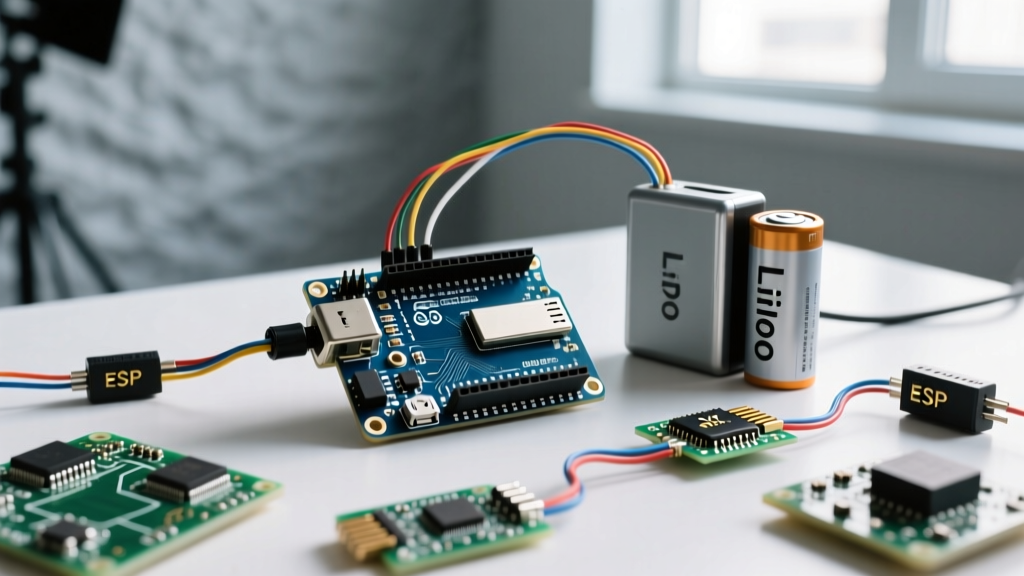
Transitioning an Arduino project from a USB wall-wart to a standalone field deployment is a rite of passage for makers. However, knowing how to power Arduino from battery efficiently requires more than just taping a 9V battery to the barrel jack. A standard Arduino Uno can drain a 9V alkaline battery in less than 15 hours, while an optimized barebones AVR circuit can run for years on the same energy budget. The secret lies in understanding battery chemistry discharge curves, voltage regulator topology, and silicon-level sleep states.
In 2026, with the proliferation of high-density lithium chemistries and ultra-low-quiescent switching regulators, there is no excuse for premature battery death in IoT and remote sensing projects. This guide breaks down the exact hardware modifications and software routines required to maximize your off-grid runtime.
Battery Chemistries: Matching the Discharge Curve
Not all batteries are created equal. The ATmega328P microcontroller at the heart of most Arduinos operates natively between 1.8V and 5.5V, depending on the clock speed. Selecting the right chemistry dictates whether you need a step-up, step-down, or direct connection.
| Chemistry (Configuration) | Nominal Voltage | Fresh / Full Charge | Cutoff / Dead | Energy Density & Notes |
|---|---|---|---|---|
| Alkaline AA (x4 in series) | 6.0V | 6.4V | 3.6V | Poor voltage stability; steep drop-off under load. |
| NiMH AA (x4 in series) | 4.8V | 5.6V | 4.0V | Flat discharge curve, but 4.8V is too low for Uno's 5V regulator. |
| LiPo (1S Cell) | 3.7V | 4.2V | 3.0V | Excellent density. Requires a boost converter for 5V logic. |
| LiFePO4 (1S Cell) | 3.2V | 3.6V | 2.5V | Safest lithium chemistry; flatter curve than LiPo, ideal for 3.3V Pro Minis. |
Expert Insight: Avoid 9V PP3 alkaline batteries entirely. They are constructed from six tiny AAAA cells in series, resulting in massive internal resistance and abysmal mAh-to-volume ratios. A standard 2000mAh 18650 Li-ion cell costs roughly $4.50 and holds nearly 15 times the usable energy of a $3.00 9V alkaline.
The Linear Regulator Problem: Heat and Dropout
If you plug a 7.4V Li-ion pack into the Arduino Uno's Vin pin, the onboard NCP1117ST50T3G (or AMS1117-5.0 on clones) linear regulator steps it down to 5V. Linear regulators operate by burning excess voltage as heat. If your circuit draws 100mA at 5V, and you feed it 9V, the regulator dissipates (9V - 5V) * 0.1A = 400mW as pure waste.
Furthermore, linear regulators suffer from dropout voltage. The NCP1117 requires a minimum headroom of about 1.1V. This means to get a stable 5V out of the 5V pin, you must feed at least 6.1V into the Vin pin. If you use 4x NiMH AA batteries (nominal 4.8V), the regulator cannot bridge the gap, resulting in a 4.2V output that triggers brown-out resets on the ATmega328P.
The Quiescent Current Tax
Even when your Arduino is doing absolutely nothing, the onboard linear regulator draws a quiescent current (Iq) of roughly 5mA to 10mA just to keep its internal bandgap reference alive. Over a month, that phantom draw alone consumes nearly 4,000 mAh—enough to completely drain a standard 18650 cell without running a single line of code.
Bypassing the Regulator: The 5V Pin Strategy
To achieve high efficiency, you must bypass the Arduino's linear regulator entirely. The modern standard for off-grid MCU deployments is to use a switching buck-boost regulator wired directly to the board's 5V pin.
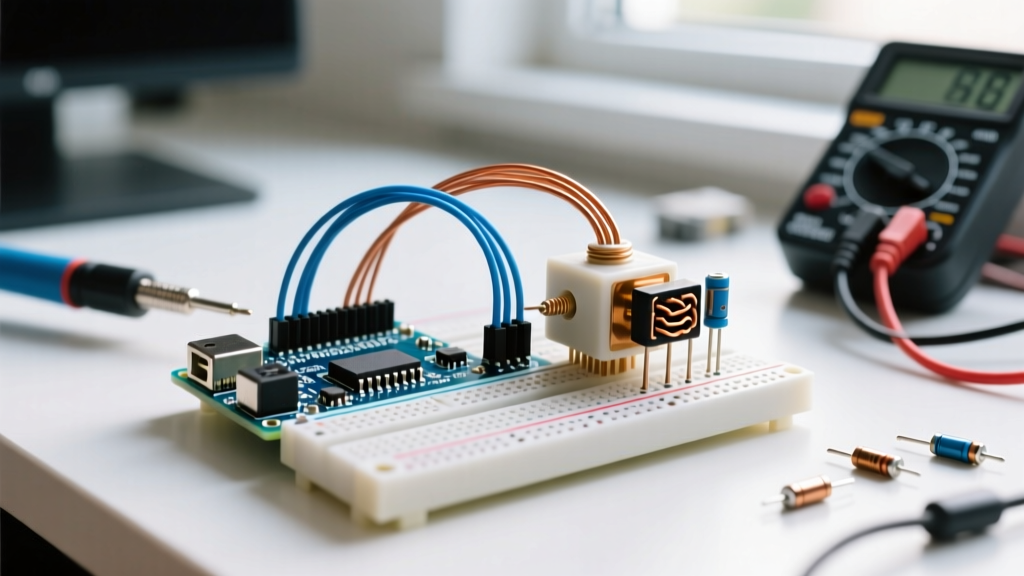
Switching regulators use inductors to transfer energy, routinely achieving 85% to 95% efficiency regardless of the input-to-output voltage differential. A highly regarded module in the maker community is the Pololu S7V8F5 step-up/step-down voltage regulator. It accepts inputs from 2.7V to 11.8V, outputs a rock-solid 5V, and boasts a quiescent current of just 1mA. By feeding a 1S LiPo (3.0V - 4.2V) into this module, and wiring the module's VOUT directly to the Arduino's 5V pin, you eliminate the linear regulator's dropout issues and thermal waste.
Warning: The 5V pin on standard Arduinos bypasses reverse-polarity protection diodes. If you accidentally swap VCC and GND from your switching regulator, you will instantly destroy the ATmega328P and the USB-to-Serial bridge.
Calculating Battery Life and the Sleep Imperative
Let us run a real-world calculation for an environmental sensor logging data every 10 minutes using an Arduino Nano clone and a 2500mAh 18650 Li-ion cell.
- Active Current: The Nano draws roughly 45mA (ATmega328P + LEDs + CH340G USB chip).
- Continuous Runtime: 2500mAh / 45mA = 55.5 hours (about 2.3 days).
To extend this to months, we must utilize the microcontroller's hardware sleep modes. According to the Microchip ATmega328P datasheet, the SLEEP_MODE_PWR_DOWN state shuts off the CPU, ADC, and timers, leaving only the asynchronous timer and pin-change interrupts active. In this state, the ATmega328P draws approximately 0.1µA at 3.3V.
However, the board-level components will ruin your sleep current. The onboard power LED draws 3mA. The CH340G USB-to-serial chip draws 15mA continuously, even when the main MCU is asleep. For true low-power deployments, you must use an Arduino Pro Mini (which lacks the USB chip) and physically desolder the power LED and its current-limiting resistor.
Implementing AVR Sleep in Code
To put the board to sleep, you must interact with the AVR sleep library. The AVR Libc Sleep Group provides the necessary macros. A standard wake-up cycle relies on a hardware interrupt (e.g., an RTC alarm pin or a reed switch) triggering an ISR (Interrupt Service Routine) that wakes the CPU.
#include <avr/sleep.h>
#include <avr/power.h>

void goToSleep() {
  set_sleep_mode(SLEEP_MODE_PWR_DOWN);
  sleep_enable();
  // Disable ADC to save ~300µA
  ADCSRA &= ~(1<<ADEN);
  sleep_mode(); // CPU halts here
  // Wakes up here after interrupt
  sleep_disable();
  ADCSRA |= (1<<ADEN); // Re-enable ADC
}
Real-World Failure Modes and Edge Cases
When designing battery-powered MCU circuits, theoretical math often collides with hardware realities. Watch out for these specific failure modes:
1. Brown-Out Detection (BOD) Phantom Drain
The ATmega328P features a Brown-Out Detection circuit that monitors supply voltage and triggers a reset if it dips below a threshold (usually 4.3V or 2.7V, depending on fuse settings). In sleep mode, the BOD circuit remains active and consumes roughly 20µA to 40µA. While small, over a year, this adds up. You can disable the BOD in software right before entering sleep by setting the BODS and BODSE bits in the MCUCR register, dropping the sleep current back to the silicon's baseline 0.1µA.
2. Lithium Over-Discharge Swelling
If a LiPo cell is drained below 2.5V, the internal chemistry degrades, leading to copper dendrite formation, internal short circuits, and physical swelling (the infamous 'spicy pillow'). Never wire a raw LiPo directly to an MCU without a protection circuit. Always use a battery management system (BMS) board or a specialized charger/booster module that features an automatic low-voltage cutoff (LVC) at 3.2V.
3. USB Backfeeding Catastrophes
If you wire a regulated 5V battery source to the Arduino's 5V pin, and then plug the USB cable into your PC to debug the code, you create a direct electrical bridge between your PC's USB 5V rail and your battery's 5V rail. If the battery is sitting at 4.8V and the PC pushes 5.2V, current will backfeed into the battery, potentially causing a fire. Always use a Schottky diode (like a 1N5817, dropping ~0.3V) on the battery feed line, or physically disconnect the battery when uploading code via USB.
Summary Decision Matrix
To quickly determine your power architecture, use this framework:
- Weekend Project / Indoor Sensor: 4x AA NiMH into Vin pin. Accept the linear regulator inefficiency for the sake of simplicity.
- 1-Month Field Logger: 1S 18650 Li-ion + Pololu S7V8F5 buck-boost wired to the 5V pin on an Arduino Pro Mini. LED removed.
- Multi-Year Remote Node: Barebones ATmega328P on a custom PCB running at 3.3V / 8MHz, powered directly by a 3.6V ER14250 Lithium Thionyl Chloride (Li-SOCl2) primary cell, utilizing Watchdog Timer sleep cycles.
Mastering how to power Arduino from battery is ultimately an exercise in eliminating waste—wasted heat from linear regulators, wasted electrons from quiescent draws, and wasted CPU cycles from idle polling. By selecting the right chemistry and leveraging silicon-level sleep states, you transform a power-hungry development board into a resilient, long-term autonomous node.