
Introduction to Joystick and Arduino Integration
Integrating a joystick and Arduino microcontroller is a foundational skill for robotics, RC vehicles, and interactive UI projects. However, moving beyond basic 'plug-and-play' tutorials requires a deep understanding of analog-to-digital conversion (ADC) mechanics, signal noise mitigation, and software deadzone calibration. Most beginners simply wire a KY-023 module to an Arduino Uno, read the analog pins, and accept the jittery, uncalibrated output. In 2026, with maker projects demanding higher precision for servo control and navigation, this approach is no longer sufficient.
This configuration guide dissects the electromechanical reality of analog joysticks, addresses the inherent flaws of the ATmega328P ADC when sampling multiplexed pins, and provides a robust software framework for mapping raw voltage data into clean, actionable control vectors.
Hardware Selection Matrix: Analog vs. Digital Interfaces
Before writing configuration code, you must select the right hardware for your tolerance requirements. The standard analog potentiometer-based joystick is ubiquitous, but digital I2C alternatives offer distinct advantages for complex builds.
| Module / Breakout | Interface | Resolution | Est. Price (2026) | Best Use Case |
|---|---|---|---|---|
| KY-023 Analog Module | Analog (Dual 10kΩ Pots) | 10-bit (via MCU ADC) | $2.50 - $4.00 | Prototyping, basic RC toys, low-budget arrays |
| SparkFun Thumb Joystick Breakout | Analog (Precision Pots) | 10-bit (via MCU ADC) | $14.95 - $18.00 | High-reliability robotics, medical UI prototyping |
| Adafruit Mini I2C Gamepad | Digital (I2C via Seesaw) | 10-bit (Internal ADC) | $9.50 - $12.00 | Pin-constrained MCUs, multi-joystick arrays, noise-heavy environments |
For this guide, we focus primarily on the analog KY-023 and similar dual-axis potentiometer joysticks, as they present the most significant configuration challenges regarding signal integrity and calibration. For deeper hardware teardowns, refer to the SparkFun Thumb Joystick Hookup Guide, which details the mechanical gimbal and spring tensioning.
Precision Wiring and Signal Noise Mitigation
The most common failure mode in joystick and Arduino configurations is ADC jitter. The wipers inside the 10kΩ linear taper (B103) potentiometers have high impedance. This high impedance turns the analog traces into antennas, picking up 50/60Hz mains hum and digital switching noise from the microcontroller itself.
The Decoupling Imperative
Do not simply wire VRx to A0 and VRy to A1 and call it a day. To achieve a stable baseline, you must implement local decoupling.
- Power: Connect VCC to the Arduino 5V pin and GND to GND.
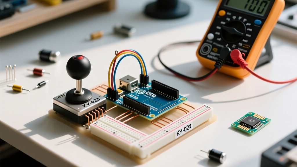
- Decoupling Capacitor: Solder a 0.1µF (100nF) ceramic capacitor directly across the VCC and GND pins on the joystick PCB. This filters high-frequency digital noise before it reaches the potentiometer tracks.
- Analog Routing: Keep the wires from VRx and VRy to the Arduino analog pins as short as possible. Avoid routing them parallel to digital PWM lines or motor controller outputs.
- Select Switch (SW): Connect the SW pin to a digital pin (e.g., D2). Do not use an external pull-up resistor; configure the pin using
INPUT_PULLUPin software to utilize the ATmega328P's internal 20kΩ-50kΩ resistor.
Software Configuration: Overcoming ADC Crosstalk
When reading multiple analog pins sequentially on an AVR-based Arduino (like the Uno or Nano), you will encounter ADC crosstalk. The internal sample-and-hold (S/H) capacitor requires time to charge to the voltage level of the newly selected multiplexer channel. If you read A0 (X-axis) and immediately read A1 (Y-axis), the Y-axis reading will be 'pulled' toward the X-axis voltage, resulting in ghosting and cross-axis interference.
Expert Configuration Rule: Never trust the first analogRead() after switching multiplexer channels. Always perform a dummy read and discard it, or insert a minimum 2-millisecond delay between axis reads. See the Arduino analogRead() reference for underlying ADC timing specifications.
Implementing the Double-Read Technique
Instead of relying on delay() functions which block the main loop, use the double-read method to allow the S/H capacitor to settle:
// X-Axis Configuration
analogRead(PIN_VRX); // Dummy read to set MUX and start charging S/H cap
int rawX = analogRead(PIN_VRX); // Actual stabilized read

// Y-Axis Configuration
analogRead(PIN_VRY); // Dummy read
int rawY = analogRead(PIN_VRY); // Actual stabilized read
Calibration and Deadzone Mapping Logic
Mechanical joysticks rely on a physical gimbal and centering springs. Due to manufacturing tolerances, the mechanical center almost never aligns perfectly with the electrical center (512 on a 10-bit 0-1023 scale). Your resting X and Y values will likely sit somewhere between 495 and 525. If you map these raw values directly to motor speeds, your robot will 'drift' even when the joystick is untouched.
Step 1: Establish the True Center
On boot, or via a dedicated calibration button, read the joystick at rest 50 times, average the results, and store them as centerX and centerY. For advanced noise filtering during this sampling phase, implement an exponential moving average or refer to the Arduino Smoothing Tutorial to eliminate outlier spikes.
Step 2: Define the Software Deadzone
A deadzone is a threshold around the center point where minor mechanical vibrations or electrical noise are ignored, outputting a clean '0'. A standard deadzone for analog joysticks is 5% to 8% of the total travel range.
On a 1024-step scale, a 5% deadzone equals roughly 51 steps. The configuration logic operates as follows:
- Subtract the calibrated center value from the raw reading to get a signed deviation (e.g., -512 to +511).
- Check if the absolute value of the deviation is less than the deadzone threshold (e.g., 50).
- If it is within the threshold, force the output to 0.
- If it is outside the threshold, map the remaining range to your desired output scale (e.g., -100 to +100 for differential drive motor control).
Step 3: Non-Linear Mapping for Precision Control
Human thumbs do not move with linear precision. For fine motor control (like camera panning or robotic arm manipulation), configure a parabolic or cubic mapping curve rather than a standard linear map() function. By squaring the normalized input and re-applying the sign, you create a curve where small physical movements yield tiny output changes, while full deflections yield maximum power.
Troubleshooting Common Failure Modes
Even with perfect wiring, edge cases will emerge during field testing. Use this diagnostic matrix to resolve anomalous behaviors:
- Symptom: The Select (Z-axis) button triggers randomly.
Cause: Floating pin or switch bounce.
Fix: Ensure you are usingpinMode(SW_PIN, INPUT_PULLUP). If physical switch bounce persists, implement a 50ms software debounce timer rather than relying on basicdelay()state changes. - Symptom: Y-axis values drift when the X-axis is moved.
Cause: ADC multiplexer crosstalk or shared ground impedance.
Fix: Implement the double-read technique outlined above. If the issue persists, verify that the GND trace on the joystick PCB is not cracked, and ensure the Arduino's 5V rail is not sagging under load. - Symptom: Inverted axis control (Up registers as Down).
Cause: The PCB orientation relative to the gimbal mechanics varies wildly among cheap KY-023 clones.
Fix: Do not physically rewire. Simply invert the logic in software by subtracting the mapped value from your maximum target value (e.g.,output = 100 - mapped_val).
Conclusion
Successfully mastering joystick and Arduino configuration requires looking past the basic schematic. By addressing ADC crosstalk, implementing hardware decoupling, and writing robust deadzone calibration routines, you transform a cheap, jittery analog component into a precise, reliable human-machine interface. Whether you are building a 2026 autonomous rover override controller or a custom MIDI instrument, these foundational principles ensure your input data is as clean as your output logic.