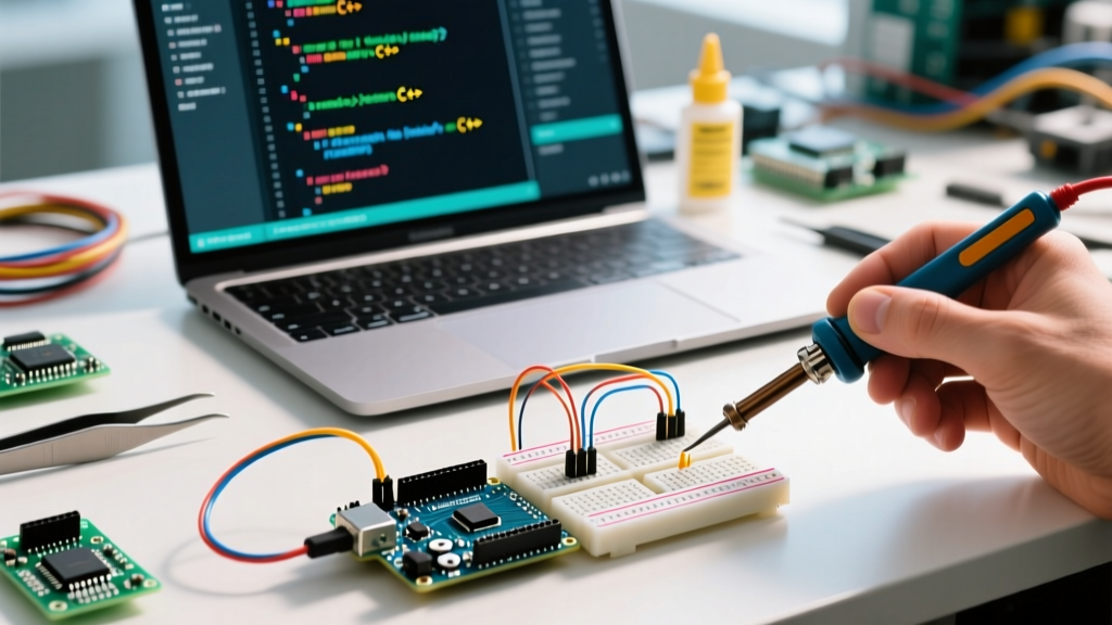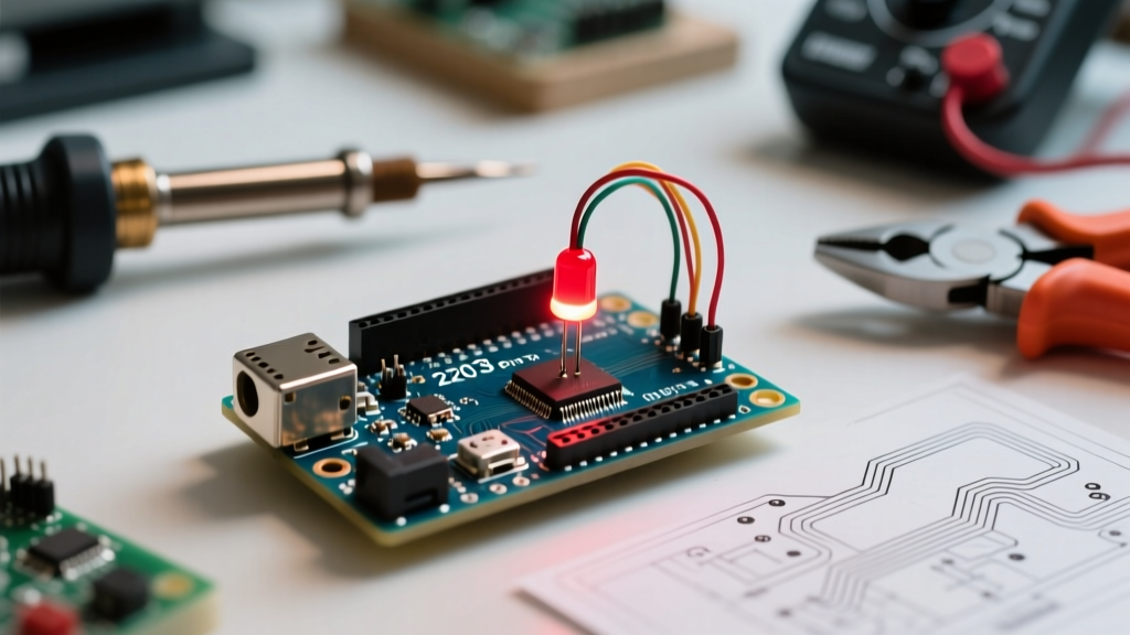

The 'Hello World' of Microcontrollers: When the Arduino LED Blink Fails
The classic Arduino LED blink sketch is universally recognized as the 'Hello World' of embedded systems. It is the very first test makers run to verify their toolchain, microcontroller, and basic circuitry. But what happens when you hit upload, and absolutely nothing happens? A failed blink test doesn't necessarily mean your board is dead. In 2026, with the proliferation of advanced Arduino IDE 2.x environments, diverse clone boards, and complex 3.3V logic architectures, an Arduino LED blink failure can stem from a dozen different software or hardware bottlenecks.
This comprehensive troubleshooting guide bypasses generic advice and dives deep into the exact failure modes of Pin 13, the onboard 'L' LED circuitry, and external breadboard wiring. We will systematically isolate whether your issue lies in the IDE configuration, the bootloader, the ATmega328P silicon, or the external components.
Phase 1: IDE & Upload Verification (The Software Layer)
Before touching a multimeter, we must verify that the compiled machine code is actually reaching the microcontroller's flash memory. The most common point of failure for beginners and veterans alike is a silent upload failure in the Arduino IDE.
1. Board and Port Mismatches in IDE 2.3+
Modern Arduino IDE versions utilize a dynamic board detection system that frequently misidentifies clone boards. If you are using a third-party Uno clone equipped with a CH340C or CP2102 USB-to-serial chip instead of the official ATmega16U2, the IDE may default to a generic serial port without applying the correct reset pulse (DTR/RTS) required to trigger the bootloader.
- The Fix: Open the Boards Manager and ensure you have the latest CH340 drivers installed. According to the official Arduino support documentation for CH340 chips, Windows 11 users often need to manually override Windows Update drivers with the WCH vendor drivers to restore the auto-reset functionality.
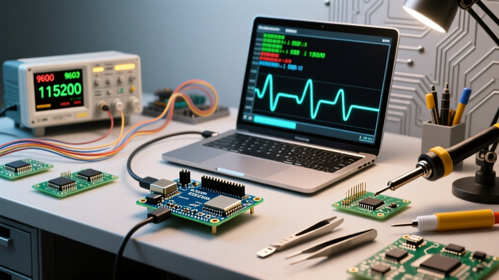
- Verification: Watch the 'RX' and 'TX' SMD LEDs during upload. If they do not flicker rapidly, your code is not transmitting. Check your USB cable—up to 30% of generic micro-USB cables on the market are 'charge-only' and lack the D+/D- data lines.
2. The 'L' LED Bootloader Pulse Code
When you press the physical reset button on an Arduino Uno R3, the ATmega328P bootloader executes. During this ~500ms window, the onboard 'L' LED (tied to Pin 13) will pulse.
Diagnostic Rule of Thumb: If the 'L' LED pulses 3 times quickly and then turns off, the bootloader is intact and waiting for code. If it fades slowly or remains solidly lit without pulsing, your bootloader is likely corrupted or the wrong fuse bits have been burned via an external ISP programmer.
Phase 2: On-Board LED (Pin 13) Hardware Diagnostics
If the IDE confirms 'Done uploading' but the onboard LED remains dark, we must investigate the physical circuit. Pin 13 is not created equal across all Arduino form factors.
The Uno R3 Op-Amp Buffer Quirk
Many makers assume Pin 13 directly drives the onboard 'L' LED. On the official Arduino Uno R3, this is false. To prevent the LED from drawing current away from sensitive SPI peripherals (like the MOSI line during SD card operations), the official Uno R3 schematic routes Pin 13 through an LMV358 dual operational amplifier configured as a unity-gain buffer before hitting the LED resistor and SMD diode.
- Set your multimeter to DC Voltage (20V range).
- Probe Pin 13 on the female header while the blink sketch is running (set the delay to 1000ms for easy reading).
- Read the Output: If you see a clean square wave oscillating between 0.0V and 4.8V, the ATmega328P is functioning perfectly. The fault lies downstream.
- Probe the Op-Amp: Locate the LMV358 chip (U5A on the schematic). Probe the output pin of the op-amp. If the input is toggling but the output is stuck at 0V, the op-amp has failed (a known issue if a user accidentally shorted Pin 13 to 5V or GND while using it as an SPI clock line).
The Nano Direct-Drive Architecture
Conversely, the Arduino Nano and Nano Every often route the microcontroller pin directly through a simple 1kΩ current-limiting resistor to the LED. If a Nano's 'L' LED is dead but Pin 13 outputs 5V, the SMD LED itself has burned out due to thermal overstress or reverse polarity voltage spikes.
Phase 3: External LED Wiring & Component Failures
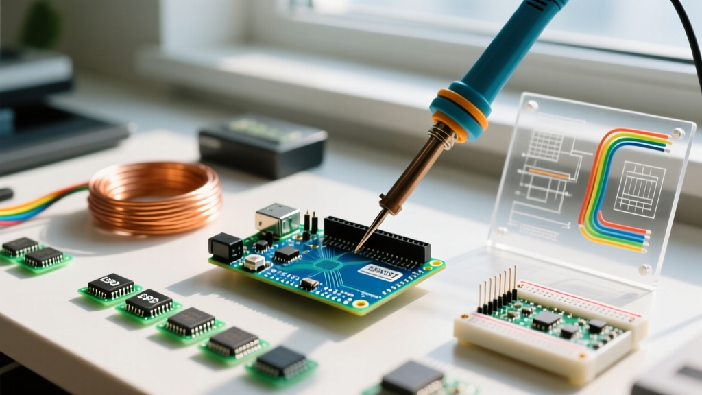
If the onboard LED works but your external breadboard Arduino LED blink circuit fails, the issue is almost always rooted in basic electronics miscalculations or breadboard continuity faults.
Calculating the Correct Current-Limiting Resistor
Failing to use a resistor will instantly destroy the ATmega328P's GPIO pin (max absolute rating is 40mA, recommended is 20mA). However, using the wrong resistor can result in an LED that is too dim to see, leading to a false 'blink failure' diagnosis.
| Board Logic Level | LED Forward Voltage (Vf) | Target Current (If) | Calculated Resistor (Ohm's Law) | Standard E12 Value to Use |
|---|---|---|---|---|
| 5V (Uno R3, Mega 2560) | 2.0V (Standard Red) | 20mA | (5 - 2.0) / 0.02 = 150Ω | 150Ω or 220Ω |
| 3.3V (Zero, Portenta, ESP32) | 2.0V (Standard Red) | 20mA | (3.3 - 2.0) / 0.02 = 65Ω | 68Ω or 100Ω |
| 5V (Uno R3, Mega 2560) | 3.2V (Blue/White) | 20mA | (5 - 3.2) / 0.02 = 90Ω | 100Ω |
Verifying LED Polarity and the 'Diode Test' Mode
LEDs are diodes; they only pass current in one direction. The longer leg is the anode (+), and the shorter leg is the cathode (-). If you have trimmed the legs, look inside the epoxy lens: the smaller metal anvil is the anode, and the larger flat plate is the cathode.
The Multimeter Test: Switch your multimeter to Diode Test Mode (the symbol with an arrow and a line). Place the red probe on the anode and the black probe on the cathode. A healthy red LED will show a voltage drop of ~1.6V to ~2.0V and emit a faint glow. If the meter reads 'OL' (Open Loop), reverse the probes. If it reads 'OL' in both directions, the internal wire bond of the LED has snapped.
Advanced Edge Cases: Timer Conflicts and PWM Interference
If your hardware checks out but the blink timing is erratic, or the LED behaves like it's fading rather than snapping on and off, you are likely experiencing a software conflict.
Timer1 and the Servo Library
On the ATmega328P, Pin 13 is tied to the SPI SCK line, but it is also heavily utilized by hardware timers. If your sketch includes the Servo.h library, be aware that the Servo library commandeers Timer1. While Timer1 doesn't directly control Pin 13's basic digital I/O, certain third-party motor and PWM libraries mapped to Pins 9 and 10 (which share Timer1) can cause interrupt service routines (ISRs) to block the delay() function, making your blink appear to freeze or stutter.
The 'Fading' LED Bug (PWM Residue)
Did you previously run a sketch utilizing analogWrite(13, value)? Pin 13 supports PWM on the Uno. If your board was reset improperly during a PWM write, the hardware timer registers may retain residual configuration states upon reboot, causing the LED to glow dimly or 'breathe' before the digitalWrite() function in your new Blink sketch overrides it. Always explicitly declare pinMode(13, OUTPUT); in your void setup() to force the hardware timer to release the pin back to standard GPIO mode.
Summary Diagnostic Matrix
Use this quick-reference matrix to isolate your Arduino LED blink failure:
| Observed Symptom | Probable Root Cause | Required Action |
|---|---|---|
| 'L' LED stays solid ON, no upload | Bootloader corruption / stuck in loop | Re-burn bootloader via USBasp ISP |
| IDE says 'Done', LED is OFF | Wrong board selected (e.g., Uno vs Nano) | Verify Tools > Board selection |
| External LED is extremely dim | Incorrect resistor math / 3.3V logic mismatch | Recalculate Ohm's law for V_source |
| Pin 13 outputs 5V, 'L' LED is OFF | Blown LMV358 op-amp or dead SMD LED | Use external LED on Pin 13 header |
| Upload fails, RX/TX don't flash | Charge-only USB cable or missing CH340 driver | Swap cable / install WCH drivers |
Conclusion
An Arduino LED blink failure is rarely a mystery; it is simply a breakdown in the chain between software compilation, USB serial transmission, bootloader execution, and physical electron flow. By leveraging a multimeter to verify the LMV358 buffer on the Uno R3, ensuring your current-limiting resistors match your specific logic voltage, and verifying USB data-line integrity, you can resolve 99% of all blink-related issues in under ten minutes. Keep this guide bookmarked for your next breadboard debugging session.