
Why Migrate from 8-Bit AVR to 32-Bit ARM?
For years, the ATmega328P (the heart of the Arduino Uno) has been the default choice for makers. However, as projects demand higher clock speeds, more flash memory, and advanced peripherals like hardware floating-point units (FPU) or multiple SPI/I2C buses, 8-bit AVRs hit a hard ceiling. This is where learning how to run Arduino on STM32 microcontrollers becomes a game-changer. By leveraging the official STM32duino core, you can program 32-bit ARM Cortex-M chips using the exact same Arduino IDE and C++ syntax you already know.
In this comprehensive 2026 guide, we will walk through the exact hardware prerequisites, IDE configuration, and wiring required to successfully flash and debug the wildly popular STM32F103C8T6 (Blue Pill) and STM32F411CEU6 (Black Pill) development boards.
Hardware Prerequisites and Board Selection
Before diving into the software, you need the right hardware. The maker market is flooded with STM32 development boards, but two form factors dominate the DIY space due to their low cost and breadboard-friendly layouts.
| Feature | Blue Pill (STM32F103C8T6) | Black Pill (STM32F411CEU6) | Arduino Uno (ATmega328P) |
|---|---|---|---|
| Architecture | ARM Cortex-M3 (32-bit) | ARM Cortex-M4F (32-bit) | AVR (8-bit) |
| Clock Speed | 72 MHz | 100 MHz | 16 MHz |
| Flash Memory | 64KB (Often 128KB in reality) | 512KB | 32KB |
| SRAM | 20KB | 128KB | 2KB |
| Approx. Cost (2026) | $3.50 - $5.00 | $6.50 - $9.00 | $15.00 - $27.00 |
Required Tools:
- Development Board: One of the STM32 boards listed above.
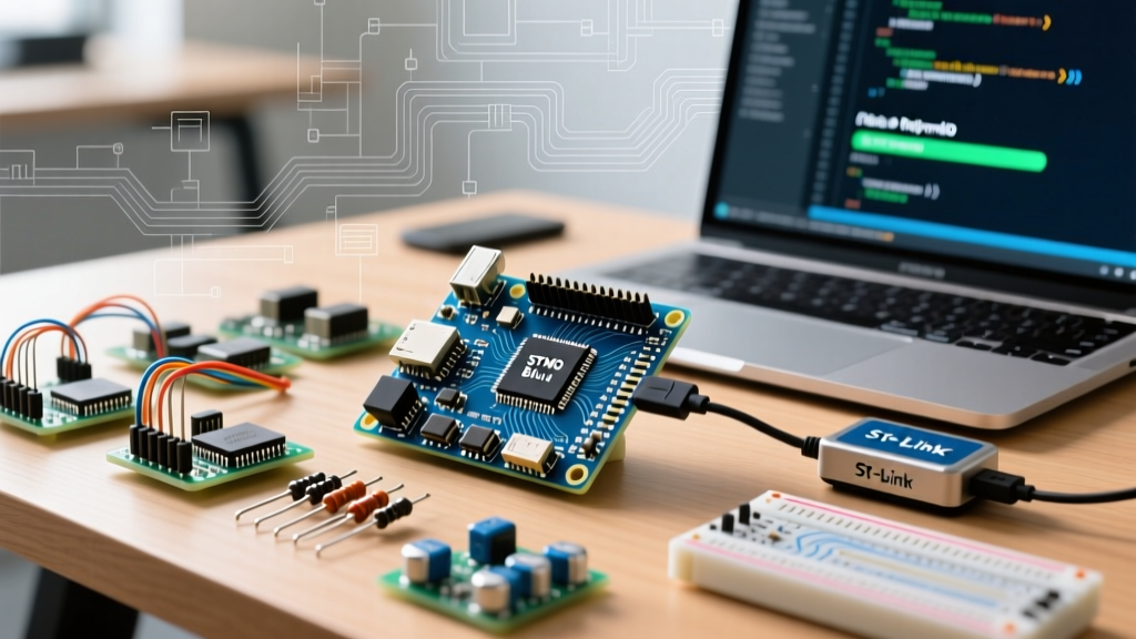
- Programmer: An ST-Link V2 clone (approx. $2.50) or genuine ST-Link V3. While serial uploading is possible, SWD (Serial Wire Debug) via an ST-Link is vastly superior for debugging and bypasses bootloader jumper configurations.
- Jumper Wires: Female-to-female Dupont wires for SWD connections.
Step 1: Installing the STM32duino Core in Arduino IDE 2.x
To run Arduino on STM32 hardware, you must install the official board definitions maintained by STMicroelectronics and the open-source community. According to the STM32duino GitHub Wiki, the core supports over 150 different STM32 microcontrollers.
Adding the Board Manager URL
- Open Arduino IDE 2.x and navigate to File > Preferences (or Arduino IDE > Settings on macOS).
- Locate the Additional boards manager URLs field.
- Paste the following official JSON URL:
https://github.com/stm32duino/BoardManagerFiles/raw/main/package_stmicroelectronics_index.json - Click OK to save.
Installing the Core
- Open the Board Manager from the left-hand sidebar.
- Search for STM32.
- Install the package named STM32 MCU based boards by STMicroelectronics. (Note: This download is roughly 400MB due to the inclusion of the ARM GCC toolchain and CMSIS libraries, so allow a few minutes for extraction).
Step 2: Wiring the ST-Link V2 Programmer
Unlike AVRs that use ISP, modern STM32 chips utilize the Serial Wire Debug (SWD) protocol. This requires only four connections to achieve both programming and real-time serial debugging.
| ST-Link V2 Pin | STM32 Blue/Black Pill Pin | Function |
|---|---|---|
| 3.3V | 3.3V | Power and Logic Level Reference |
| GND | GND | Common Ground |
| SWDIO | DIO (or SWDIO) | Serial Wire Data I/O |
| SWCLK | CLK (or SWCLK) | Serial Wire Clock |
Critical Warning: Never connect the 5V pin from the ST-Link to the 3.3V pin on the STM32 board. STM32 I/O pins are strictly 3.3V tolerant (with very few 5V-tolerant exceptions). Feeding 5V into the 3.3V rail will instantly destroy the internal voltage regulator and fry the ARM core.
Step 3: Configuring the IDE and Uploading Your First Sketch
With the hardware wired, open the classic Blink example (File > Examples > 01.Basics > Blink). The onboard LED on the Blue Pill is tied to pin PC13, which is active LOW. The standard Blink sketch will work without modification because the STM32duino core maps the `LED_BUILTIN` macro to PC13 automatically.
Crucial Tools Menu Settings
Navigate to the Tools menu and configure the following parameters exactly:
- Board: Generic STM32F103C series (or Generic STM32F411C series for Black Pill).
- Board part number: BluePill F103C8 (or F103CB if your board has 128KB flash).
- Upload method: STM32CubeProgrammer (SWD).
- Optimize: Smallest (-Os default).
- U(S)ART support: Enabled (generic 'Serial').
Select your ST-Link from the Port dropdown. If the ST-Link does not appear, ensure you have installed the latest ST-Link drivers from the official STM32CubeProgrammer page on STMicroelectronics' website. Click Upload. The IDE will compile the ARM binary, invoke the programmer, and the LED on PC13 should begin blinking.
Step 4: The Serial Upload Fallback (No ST-Link Required)
If you do not have an ST-Link, you can upload via a USB-to-Serial adapter (like a CP2102 or CH340). However, this requires manual bootloader entry.
- Wire the adapter's TX to the STM32's PA10 (RX1), and RX to PA9 (TX1).
- Move the BOOT0 jumper on the STM32 board from position
0to1. - Press the RESET button on the board. This forces the chip into the factory-burned serial bootloader.
- In the Arduino IDE, change Upload method to STM32CubeProgrammer (Serial).
- Click Upload. Once finished, move BOOT0 back to
0and press RESET to run your code.
Expert Troubleshooting: Edge Cases and Hardware Flaws
Running Arduino on STM32 clone boards is highly cost-effective, but the cheap manufacturing processes introduce specific hardware flaws that stump beginners. Here is how to diagnose and fix the most common issues.
1. The Blue Pill USB Pull-Up Resistor Flaw
If you attempt to use the Blue Pill's onboard micro-USB port for native USB serial, Windows will likely report 'USB Device Not Recognized'. The official STM32 USB specification requires a 1.5kΩ pull-up resistor on the USB D+ line. However, to cut costs, many overseas factories populated the R10 resistor pad with a 10kΩ or 4.7kΩ resistor (marked 102 or 472).
The Fix: You have two options. First, use an ST-Link V2 and completely ignore the USB port for programming (relying on Serial1 via PA9/PA10 for debugging). Second, if you need native USB, use a soldering iron to bridge a standard 1.5kΩ through-hole resistor across the R10 SMD pads to bring the pull-up resistance into spec.
2. Dealing with Fake CS32F103 Clone Chips
During the global silicon shortages, many Blue Pill boards were shipped with CS32F103 chips (manufactured by Coreman) instead of genuine STMicroelectronics silicon. While mostly pin-compatible, older upload tools like dfu-util or early versions of OpenOCD fail to recognize the Coreman chip ID, resulting in a 'Target not found' error.
The Fix: The modern STM32duino core uses STM32CubeProgrammer under the hood for SWD uploads. STM32CubeProgrammer is highly resilient to clone chip IDs and will successfully flash a CS32F103 via the ST-Link V2 without any special flags. Always select STM32CubeProgrammer (SWD) in the Tools menu to bypass this issue.
3. Serial Monitor Garbage Output
If your sketch uploads successfully, but the Serial Monitor outputs garbage characters, verify your clock configuration. Some ultra-cheap STM32 boards ship with 16MHz crystals that are poorly calibrated or actually 8MHz crystals mislabeled. If the IDE assumes a 16MHz external crystal (HSE) but the board uses an 8MHz internal oscillator (HSI), baud rates will be skewed.
The Fix: In the Tools menu, locate OSC Clock Source. Change it from External Crystal (HSE) to Internal Clock (HSI). This forces the MCU to use its internal 8MHz RC oscillator, which the PLL multiplies reliably, restoring accurate UART baud rates.
Conclusion
Transitioning to 32-bit ARM architecture unlocks massive computational headroom for DSP, motor control, and complex IoT protocols. By understanding the nuances of the STM32duino core, SWD wiring, and the physical quirks of clone hardware, you can seamlessly run Arduino on STM32 platforms. For further reading on advanced peripheral mapping and DMA configuration, consult the official Arduino Core Documentation and the ST reference manuals.