
Why NTC Thermistors Demand Precise Configuration
While digital sensors like the DS18B20 dominate plug-and-play tutorials, configuring an NTC thermistor with Arduino remains the gold standard for applications requiring rapid thermal response times, ultra-low profile packaging, and high-resolution analog data. However, because NTC (Negative Temperature Coefficient) thermistors are highly non-linear, simply calling analogRead() will yield useless, erratic data. Achieving ±0.1°C accuracy requires a deliberate hardware biasing strategy, precise Steinhart-Hart mathematical modeling, and careful management of ADC (Analog-to-Digital Converter) limitations.
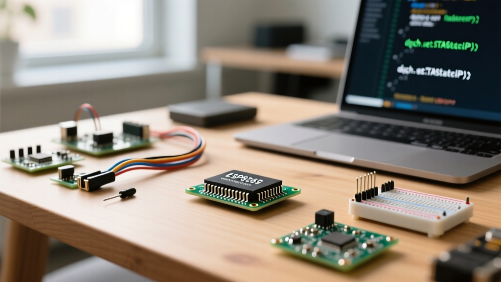
In this configuration guide, we will walk through the exact hardware and software steps to interface a precision 10K NTC thermistor—specifically the EPCOS B57891S0104F000 (±1% tolerance, ~$1.15 on Mouser)—with modern microcontrollers like the Arduino Uno R4 and ESP32-S3.
Hardware Configuration: The Voltage Divider
Microcontrollers cannot read resistance directly; they read voltage. To convert the thermistor's variable resistance into a measurable voltage, you must build a voltage divider circuit. This requires a "balance" (or series) resistor. The choice of this resistor dictates the temperature range where your ADC resolution will be highest.
Selecting the Balance Resistor
The general rule of thumb is to select a balance resistor equal to the thermistor's resistance at the center of your target temperature range. For standard room and body temperature applications (0°C to 50°C), a 10K balance resistor is ideal. For high-temperature environments (e.g., 3D printer hotends or kiln monitoring up to 120°C), the thermistor's resistance drops dramatically, requiring a lower balance resistor to keep the output voltage within the ADC's readable window.
- Component Recommendation: Use a Vishay PR02 10K 1% tolerance metal film resistor (~$0.12). Do not use standard 5% carbon film resistors; their thermal drift will introduce ±1.5°C of error before you even write a line of code.
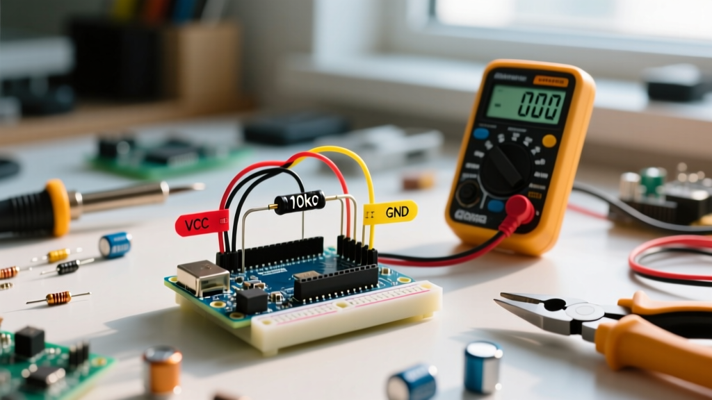
- Wiring Topology: Connect VCC (3.3V or 5V) to the balance resistor, the other end of the balance resistor to the thermistor and the analog input pin (A0), and the other end of the thermistor to GND.
Optimizing for Target Temperature Ranges
| Target Temp Range | Thermistor Nominal | Balance Resistor | ADC Sweet Spot |
|---|---|---|---|
| -40°C to 0°C | 10K @ 25°C | 30K - 50K | High Voltage (3.5V - 4.8V) |
| 0°C to 50°C | 10K @ 25°C | 10K | Mid Voltage (1.5V - 3.5V) |
| 50°C to 120°C | 10K @ 25°C | 1K - 3.3K | Low Voltage (0.2V - 1.5V) |
Mathematical Configuration: Steinhart-Hart Equation
The Beta parameter equation commonly found in basic tutorials is only accurate across a narrow 25°C window. For wide-range precision, you must configure the Steinhart-Hart equation, which models the thermistor's non-linear curve using three coefficients (A, B, and C). As detailed in Ametherm's Steinhart-Hart Application Note, the equation is:
1 / T = A + B * ln(R) + C * (ln(R))^3
Where T is temperature in Kelvin and R is the measured resistance in Ohms. For the EPCOS 10K 3988K thermistor, the coefficients are approximately:
- A = 1.009249522e-03
- B = 2.378405444e-04
- C = 2.019202697e-07
You can derive exact coefficients for your specific batch by measuring the thermistor's resistance in an ice bath (0°C), room temperature (25°C), and boiling water (100°C), then using an online Steinhart-Hart calculator to solve the system of linear equations.
Software Implementation & ADC Filtering
Raw ADC readings are inherently noisy, often fluctuating by ±3 to ±5 bits due to electromagnetic interference and internal microcontroller switching noise. To stabilize your thermistor data, implement a software low-pass filter.
The Moving Average Filter
Instead of taking a single reading, sample the analog pin 16 times in rapid succession and average the results. This technique, known as oversampling, effectively increases your ADC resolution and smooths out high-frequency noise. According to Adafruit's Thermistor Guide, combining oversampling with a floating-point exponential moving average (EMA) yields the most stable real-time temperature graphs without introducing severe reading lag.
// Exponential Moving Average Configuration
float tempEMA = 25.0; // Initialize with expected room temp
const float alpha = 0.1; // Smoothing factor (0.0 to 1.0)

void loop() {
  float rawTemp = readThermistor(); // Function containing Steinhart-Hart math
  tempEMA = (alpha * rawTemp) + ((1.0 - alpha) * tempEMA);
  Serial.println(tempEMA);
  delay(50);
}
Edge Cases: ESP32 ADC Non-Linearity
If you are configuring an NTC thermistor with an ESP32 (including the newer ESP32-S3 and C3 variants), you will encounter a critical hardware limitation: the ESP32's internal 12-bit ADC is notoriously non-linear. Readings above 3.0V and below 0.15V are highly compressed and inaccurate.
Expert Fix: Never connect a 5V voltage divider directly to an ESP32 analog pin. If your calculated voltage divider output exceeds 2.8V, you must either scale it down using a secondary resistor divider, or bypass the internal ADC entirely by using an external I2C ADC like the Texas Instruments ADS1115 (16-bit resolution, ~$4.50 on Mouser).
Troubleshooting Edge Cases: Self-Heating Errors
A common failure mode in precision thermistor configurations is "self-heating." When current flows through the thermistor to create the voltage drop, it generates internal heat ($P = V^2 / R$).
Consider a 5V Arduino Uno circuit with a 10K thermistor and 10K balance resistor. The total resistance is 20K. The power dissipated by the thermistor is roughly 0.625mW. The EPCOS datasheet specifies a dissipation constant ($\delta$) of 2 mW/°C in still air. Therefore, the self-heating error is $0.625 / 2 = 0.31°C$. In a sealed, unventilated enclosure, this error can easily exceed 1.5°C.
The Pulsed Excitation Solution
To eliminate self-heating, do not power the voltage divider continuously from the 5V or 3.3V rail. Instead, wire the top of the balance resistor to a digital GPIO pin. Set the pin to OUTPUT and drive it HIGH only for the 100 microseconds required to execute analogRead(), then immediately drive it LOW. This drops the average power dissipation to near zero, entirely negating the self-heating error while preserving battery life in IoT deployments.
Final Calibration Checklist
- Verify Resistor Tolerance: Measure your balance resistor with a multimeter and hardcode the exact value (e.g., 9982.0) into your Arduino sketch rather than assuming 10000.0.
- Use Ratiometric Readings: If using an Arduino Uno R3/R4, configure your code to calculate resistance based on the ratio of the ADC reading to the maximum ADC value (1023 or 16383), which cancels out minor fluctuations in the microcontroller's reference voltage.
- Thermal Coupling: Ensure the thermistor bead is physically isolated from the copper traces of your PCB. Copper acts as a heat sink, pulling the thermistor temperature toward the ambient PCB temperature rather than the air or liquid you are trying to measure.